
Composite cutter head

A technology of compound cutter and cutter head, which is applied in the attachments of tool holders, cutters for lathes, and manufacturing tools, etc., can solve the problems of small processing space, inability to adjust the cutter angle, and no post-process finishing, etc. The effect of solving the knife pattern problem

Pending Publication Date: 2021-10-22
FU DING ELECTRONICSAL TECH JIASHAN
View PDF9 Cites 0 Cited by
  • Summary
  • Abstract
  • Description
  • Claims
  • Application Information

AI Technical Summary

Problems solved by technology

[0002] In the face of increasingly fierce competition in the electronics industry market, customers have increasingly stringent requirements for products. Many products are not allowed to have knife lines when they are processed on the side, and they are not allowed to be finished in the post-process. Small, if you use an ordinary large cutter head, you can’t enter the cutting process, and the way of directly using the tool holder to clamp the tool, the tool angle cannot be adjusted, that is, the knife lines are serious, cannot be improved, and the cutting effect is not ideal

Method used


Image

  • Composite cutter head
  • Composite cutter head
  • Composite cutter head

Examples


Embodiment Construction

[0040] The following will clearly and completely describe the technical solutions in the embodiments of the application with reference to the accompanying drawings in the embodiments of the application. Apparently, the described embodiments are only part of the embodiments of the application, not all of them. Based on the implementation manners in this application, all other implementation manners obtained by persons of ordinary skill in the art without making creative efforts belong to the scope of protection of this application.

[0041] It should be noted that when an element is said to be "fixed" to another element, it may be directly on the other element or there may be an intervening element. When a component is said to be "connected" to another component, it may be directly connected to the other component or there may be intervening components at the same time. When a component is said to be "set on" another component, it may be set directly on the other component or i...


PUM


Abstract

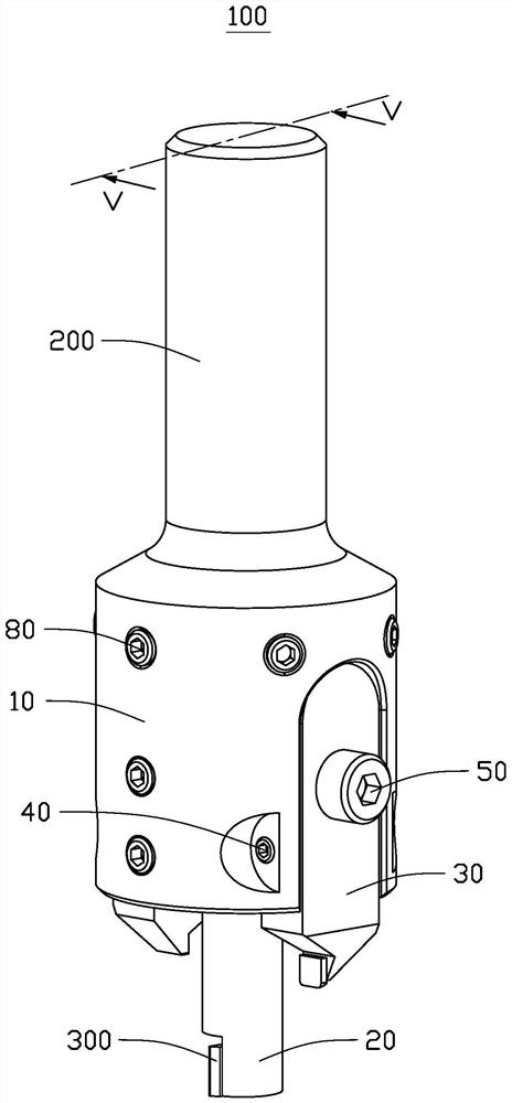
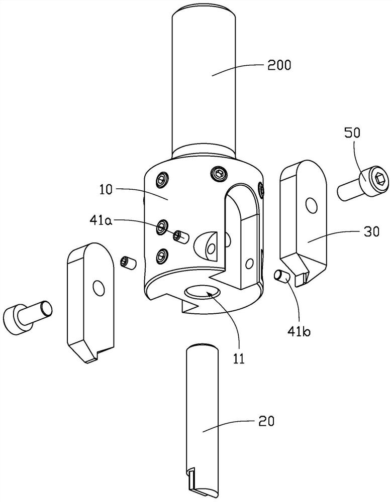
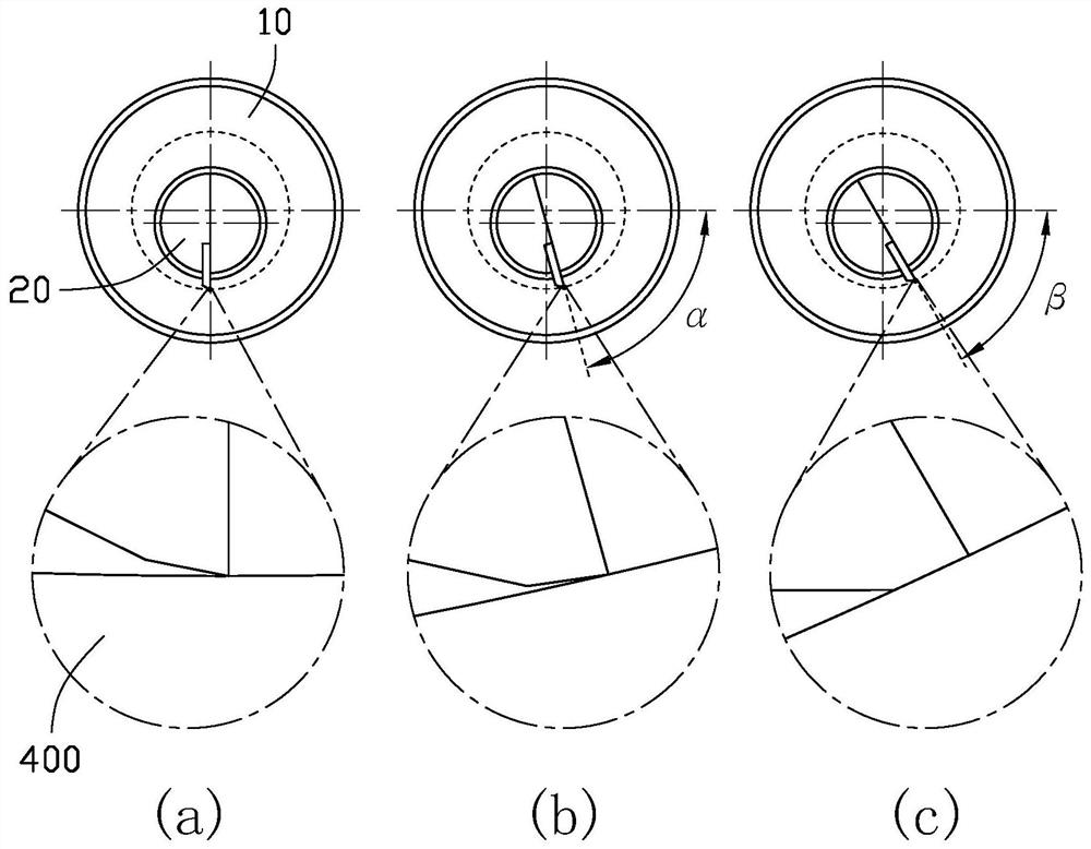
The invention discloses a composite cutter head. The composite cutter head comprises a cutter bar and a cutter head main body connected with the cutter bar, wherein a mounting hole is formed in the center of the end, away from the cutter bar, of the cutter head main body, the mounting hole is used for mounting a cutter bar type cutter, and the central axis of the mounting hole deviates from the central axis of the cutter head main body.

Description

technical field [0001] The present application relates to a composite cutter head capable of adjusting the angle of arbor-type cutters. Background technique [0002] In the face of increasingly fierce competition in the electronics industry market, customers have increasingly stringent requirements for products. Many products are not allowed to have knife lines when they are processed on the side, and they are not allowed to be finished in the post-process. Small, if you use an ordinary large cutter head, you cannot enter the cutting process, and directly use the tool holder to clamp the tool, the tool angle cannot be adjusted, that is, the tool pattern is serious, cannot be improved, and the cutting effect is not ideal. Contents of the invention [0003] In view of this, it is necessary to provide a composite cutter head capable of adjusting the angle of the cutter bar type cutter. [0004] The present application provides a composite cutterhead, which includes a cutter ...

Claims


Application Information

Patent Timeline
IPC IPC(8): B23Q3/12B23B27/00
CPCB23Q3/12B23B27/00
Inventor 谢正军瞿健李彬杜宜彪储清亮朱团辉
Owner FU DING ELECTRONICSAL TECH JIASHAN
Learn More