
A high-precision CNC grinding machine and its working method
A CNC grinding machine, high-precision technology, applied in the direction of grinding machine, grinding bed, grinding workpiece support, etc., can solve the problems of limited applicability of grinding device, weak automatic identification ability of workpiece, and increase of processing cost, so as to improve the scope of application , reduce processing costs, improve the effect of adaptability
- Summary
- Abstract
- Description
- Claims
- Application Information
AI Technical Summary
Problems solved by technology
Method used
Image

Examples
Embodiment Construction
[0036] The following description serves to disclose the present invention to enable those skilled in the art to carry out the present invention. The preferred embodiments described below are only examples, and those skilled in the art can devise other obvious variations.
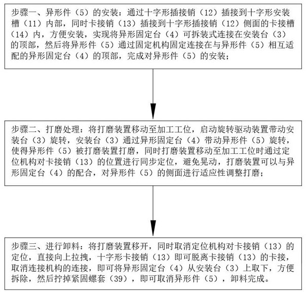
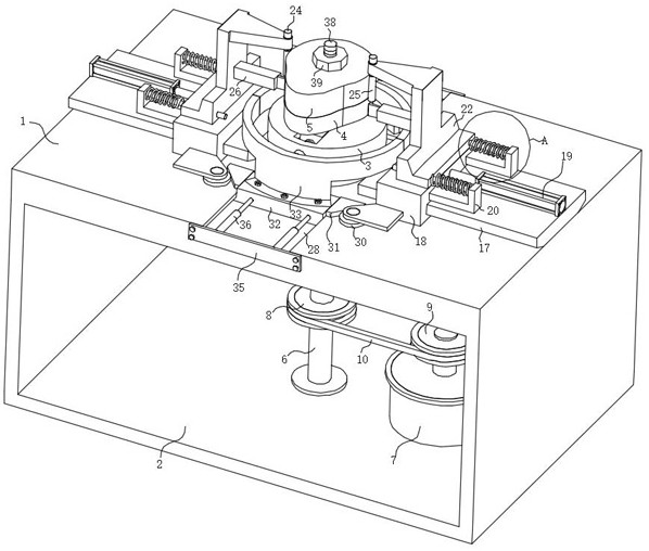
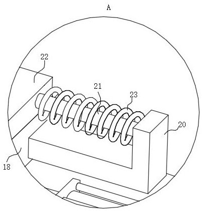
[0037] Such as Figure 1-12 A high-precision CNC grinding machine shown includes a lathe table 1, the lathe table 1 has a mounting cavity 2, and the middle position of the top of the lathe table 1 is rotatably connected to a mounting table 3, and the inside of the mounting cavity 2 is connected to a rotating drive device, and the rotating drive device It is used to drive the installation table 3 to rotate. The top of the installation table 3 is provided with a special-shaped fixed table 4. A connecting mechanism for easy disassembly is jointly connected between the special-shaped fixed table 4 and the installation table 3. The top of the special-shaped fixed table 4 is provided with a special-shaped fixed ta...
PUM
 Abstract
Description
Claims
Application Information