A vehicle-mounted image recognition device and method

An image recognition device and connecting board technology, applied in vehicle parts, transportation and packaging, machine/stand and other directions, can solve the problem of vehicle-mounted image recognition device not being able to perform comprehensive inspection, to prevent up and down movement, prevent viewing, increase The effect of stability

Active Publication Date: 2021-12-10
CHANGZHOU INST OF DALIAN UNIV OF TECH
View PDF0 Cites 0 Cited by
  • Summary
  • Abstract
  • Description
  • Claims
  • Application Information

AI Technical Summary

Problems solved by technology

[0003] In order to solve the problems raised in the above-mentioned background technology, the object of the present invention is to provide a vehicle-mounted image recognition device and method, which has the advantage of being able to conduct a comprehensive view, and solves the problem that the existing vehicle-mounted image recognition device cannot perform a comprehensive view

Method used


Image

  • A vehicle-mounted image recognition device and method
  • A vehicle-mounted image recognition device and method
  • A vehicle-mounted image recognition device and method

Examples


Embodiment 1

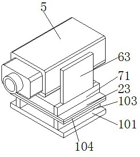
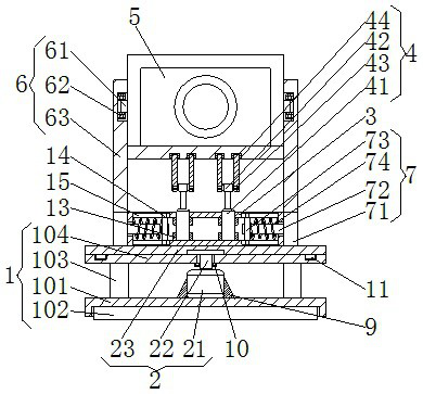
[0048] Such as Figure 1 to Figure 7 As shown, a vehicle-mounted image recognition device and method provided by the present invention include a support mechanism 1, and the support mechanism 1 includes a base 101, an adhesive plate 102, a support plate 103 and a positioning connecting plate 104, and the adhesive plate 102 is fixedly connected to the base 101 Inside, the bottom of the pasting plate 102 extends to the bottom of the base 101, the support plate 103 is fixedly connected to the top of the base 101, the positioning connecting plate 104 is fixedly connected to the top of the supporting plate 103, and the top of the positioning connecting plate 104 is provided with a rotating mechanism 2 ;

[0049] The rotating mechanism 2 includes a motor 21, an output rod 22 and an output plate 23, the motor 21 is fixedly connected to the top of the base 101, the output rod 22 is fixedly connected to the output end of the motor 21, and the top of the output rod 22 penetrates the pos...

Embodiment 2

[0073] refer to Figure 1 to Figure 6 , including the following steps:

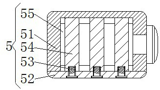
[0074]S1: The user manually pushes the positioning plate 63, the positioning plate 63 drives the limiting plate 71 to move, the limiting plate 71 compresses the return spring 74 through the limiting rod 72 and the sliding plate 73, and then the camera 5 is placed between the positioning plates 63, Loosen the positioning plate 63 again, the rotating wheel 61 is inserted into the inside of the positioning bearing 62 by the return spring 74, and then the pulling plate 44 is movably connected with the transmission rod 43, and the shooting module 553 passes through the resolution adjustment module 552 and the multi-layer shooting during use. The cooperation of the lens 551 takes pictures of the scene, and then the captured data is transferred to the inside of the Bluetooth module 554, and the data is transferred to the inside of the vehicle-mounted Bluetooth cooperation module 81 through the Bluetooth module 5...


PUM


Abstract

The invention discloses a vehicle-mounted image recognition device and method, comprising a support mechanism, the support mechanism includes a base, a pasting board, a support board and a positioning connecting board, the pasting board is fixedly connected inside the base, the pasting board The bottom of the base extends to the bottom of the base, and the support plate is fixedly connected to the top of the base. The present invention controls the left and right angles of the camera by setting a rotating mechanism, and then adjusts the up and down angles of the camera through an angle adjustment mechanism, so that the camera is facing the scene that needs attention, thereby achieving the effect of being able to conduct a comprehensive view, and solving the existing problems The problem that the vehicle-mounted image recognition device cannot be fully checked, the vehicle-mounted image recognition device and method have the advantage of being able to perform a comprehensive view, and the vehicle-mounted image recognition device will not appear dead when the user is using it, thereby ensuring car accidents and avoiding Affect the safety of others or yourself.

Description

technical field [0001] The invention relates to the technical field of image recognition devices, in particular to a vehicle-mounted image recognition device and method. Background technique [0002] The vehicle-mounted image recognition device is an image recognition device, which is mainly used on large trucks, and is used for the truck driver to check the blind spots that cannot be viewed. The identification device is prone to blind spots, which is prone to car accidents and affects the safety of others or itself. Contents of the invention [0003] In order to solve the problems raised in the above-mentioned background technology, the object of the present invention is to provide a vehicle-mounted image recognition device and method, which has the advantage of being able to conduct a comprehensive view, and solves the problem that the existing vehicle-mounted image recognition device cannot perform a comprehensive view . [0004] In order to achieve the above object, ...

Claims


Application Information

Patent Timeline
Patent Type & Authority Patents(China)
IPC IPC(8): B60R11/02B60R11/04F16M11/04F16M11/12F16M11/18F16M13/02
CPCB60R11/04B60R11/0229F16M11/04F16M11/12F16M11/18F16M13/02B60R2011/0085B60R2011/0092
Inventor 贾永涛刘鹏
Owner CHANGZHOU INST OF DALIAN UNIV OF TECH
Why Eureka
Try Eureka