Composite floor structure

A technology for combining floor slabs and inserting panels, which is applied in the direction of floor slabs, building components, building structures, etc., can solve the problems of inconvenient disassembly and assembly of profiled steel plates, and achieve the effect of easy disassembly and assembly and easy reset

Inactive Publication Date: 2021-10-26
南京明辉建设有限公司
View PDF8 Cites 0 Cited by
  • Summary
  • Abstract
  • Description
  • Claims
  • Application Information

AI Technical Summary

Problems solved by technology

[0004] However, the existing profiled steel plates and truss beams are often connected by welding, which may make it inconvenient to disassemble and assemble the profiled steel plates

Method used


Image

  • Composite floor structure
  • Composite floor structure
  • Composite floor structure

Examples


Embodiment Construction

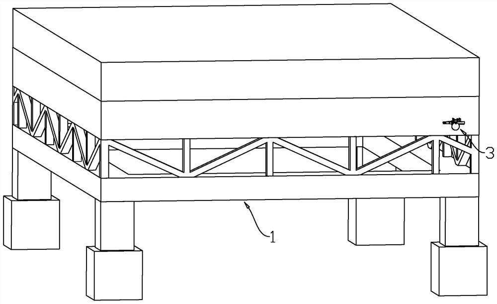
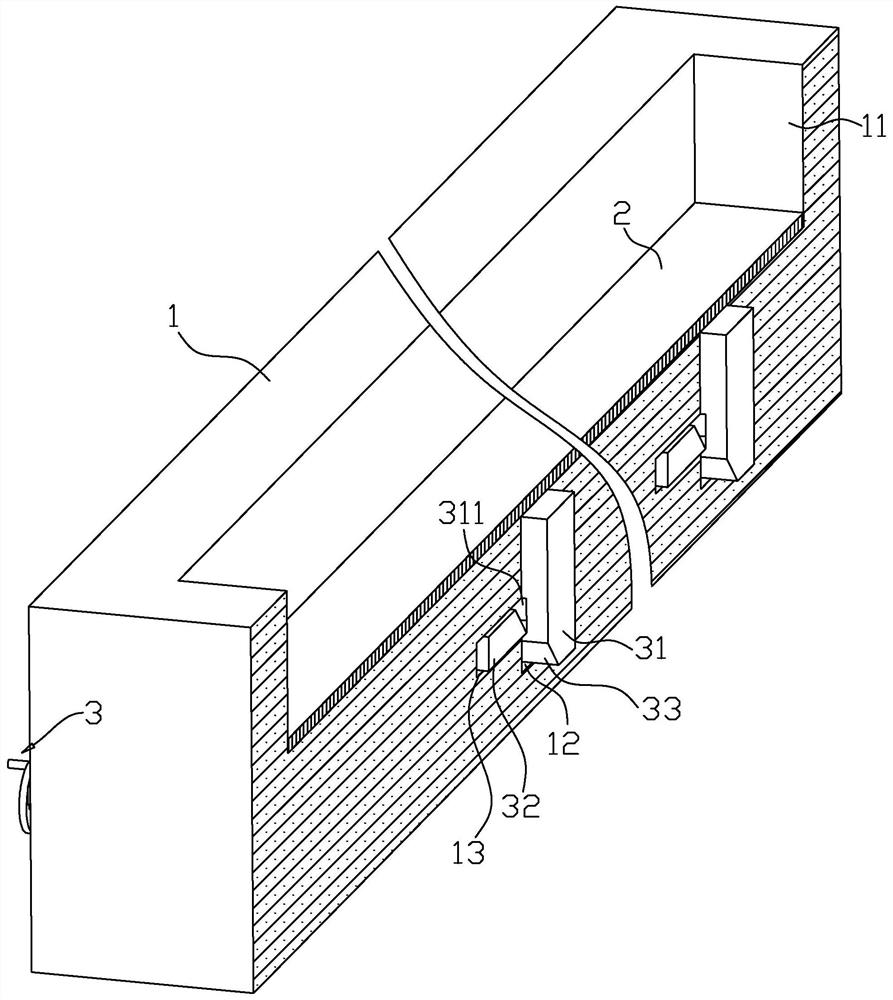
[0033] The invention discloses a composite floor structure, such as figure 1 and figure 2 As shown, it includes a truss girder 1, a profiled steel plate 2 installed on the top of the truss girder 1, and an upper plate installed on the top of the profiled steel plate 2. The top of the truss beam 1 is provided with a sinking groove 11 for placing the profiled steel plate 2. Fixing devices 3 for fixing the profiled steel plate 2 are installed at both ends of the groove 11 .

[0034] Such as figure 2 and image 3As shown, each set of fixing devices 3 includes a plurality of flashboards 31, and the flashboards 31 are vertically arranged, and one end of the sinker 11 is provided with a plurality of slots 12, and the slots 12 extend vertically, and the flashboards 31 correspond to each other one by one. Inserted in the slot 12, and the inserting plate 31 is vertically fixed on the bottom of the profiled steel plate 2, the inserting plate 31 is provided with a limiting groove 311...


PUM


Abstract

The invention discloses a composite floor structure. The composite floor structure comprises a truss girder, a profiled steel sheet and an upper layer plate, wherein a sinking groove used for containing the profiled steel sheet is formed in the top of the truss girder, fixing devices used for fixing the profiled steel sheet are installed at the two ends of the sinking groove, each fixing device comprises a plurality of inserting plates, a plurality of inserting grooves are formed in one end of the sinking groove, the inserting plates are inserted into the inserting grooves in a one-to-one correspondence mode, the inserting plates are fixedly connected to the bottom of the profiled steel sheet, limiting grooves are formed in the inserting plates, limiting plates are slidably connected into the bottom walls of one ends of the sinking grooves, the limiting plates can be inserted into the limiting grooves, inclined planes are arranged on the opposite inner sides of the limiting plates and the inserting plates respectively, and the two inclined planes are matched with each other; an elastic assembly used for driving the limiting plates to move in the direction close to the inserting grooves is installed in the bottom wall of one end of the sinking groove, and a driving mechanism used for driving the multiple limiting plates to move in the direction away from the limiting grooves is installed at one end of the sinking groove. According to the composite floor structure, the profiled steel sheet is convenient to disassemble and assemble.

Description

technical field [0001] The invention relates to the technical field of prefabricated buildings, in particular to a composite floor structure. Background technique [0002] At present, composite floor slabs can also be called floor slabs, load-bearing slabs, floor slabs, floor slabs and steel slabs. [0003] For the prior art, please refer to the Chinese utility model patent whose authorized notification number is CN207794401U, which discloses a composite floor slab, which includes a truss beam, a profiled steel plate fixed on the truss beam, and an upper plate fixed on the profiled steel plate, There are at least two hoisting rods installed on the truss beam, the hoisting rods are located under the profiled steel plate, and at least three hoisting holes are opened on the upper layer, the hoisting holes pass through the upper layer and the profiled steel plate, and the hoisting holes are located at the bottom of the hoisting rod directly above, at least one hoisting hole is ...

Claims


Application Information

Patent Timeline
Patent Type & Authority Applications(China)
IPC IPC(8): E04B5/17E04B1/38F16F15/067
CPCE04B5/17E04B1/38F16F15/067
Inventor 袁桂生张孝锐章熙康章熙玮
Owner 南京明辉建设有限公司
Why Eureka
Try Eureka