Device for preparing pile-rock interface compression shear sample and use method

A sample preparation and interface technology, applied in the field of geotechnical engineering rock-socketed pile pile-rock contact surface, can solve the problems of not considering the penetration force of concrete to surrounding rock, errors, etc., achieve low cost, reduce operation links, and simple operation Effect

Pending Publication Date: 2021-11-02
HEFEI UNIV OF TECH
View PDF0 Cites 0 Cited by
  • Summary
  • Abstract
  • Description
  • Claims
  • Application Information

AI Technical Summary

Problems solved by technology

[0003] However, this method of preparing pile-rock interface compression-shear samples does not consider the roughness of the pile-rock interface at different pile depths and the penetration of concrete to the surrounding rock under a certain grouting pressure, because the geological conditions are complex. For rock-socketed piles that bear heavy loads and have deep rock-socketed depths, due to differences in the geometry of the construction interface, pile foundations embedded in deep rock formations will form rough surfaces with different geometric shapes at the pile-rock interface at different pile depths. Under a certain grouting pressure, as the depth of the pile changes, the lithology of the formation also changes, and the penetration of concrete to the surrounding rock is also different, so that the pile-rock interface compression-shear specimen prepared by the traditional method can be used for compression. There are large errors between the strength parameters and deformation parameters of the pile-rock interface calculated by the shear test and the real situation, which cannot better reflect the pile side friction resistance value of the rock-socketed pile during the actual stress process

Method used


Image

  • Device for preparing pile-rock interface compression shear sample and use method
  • Device for preparing pile-rock interface compression shear sample and use method
  • Device for preparing pile-rock interface compression shear sample and use method

Examples


Embodiment Construction

[0036] The following will clearly and completely describe the technical solutions in the embodiments of the present invention with reference to the drawings in the embodiments of the present invention.

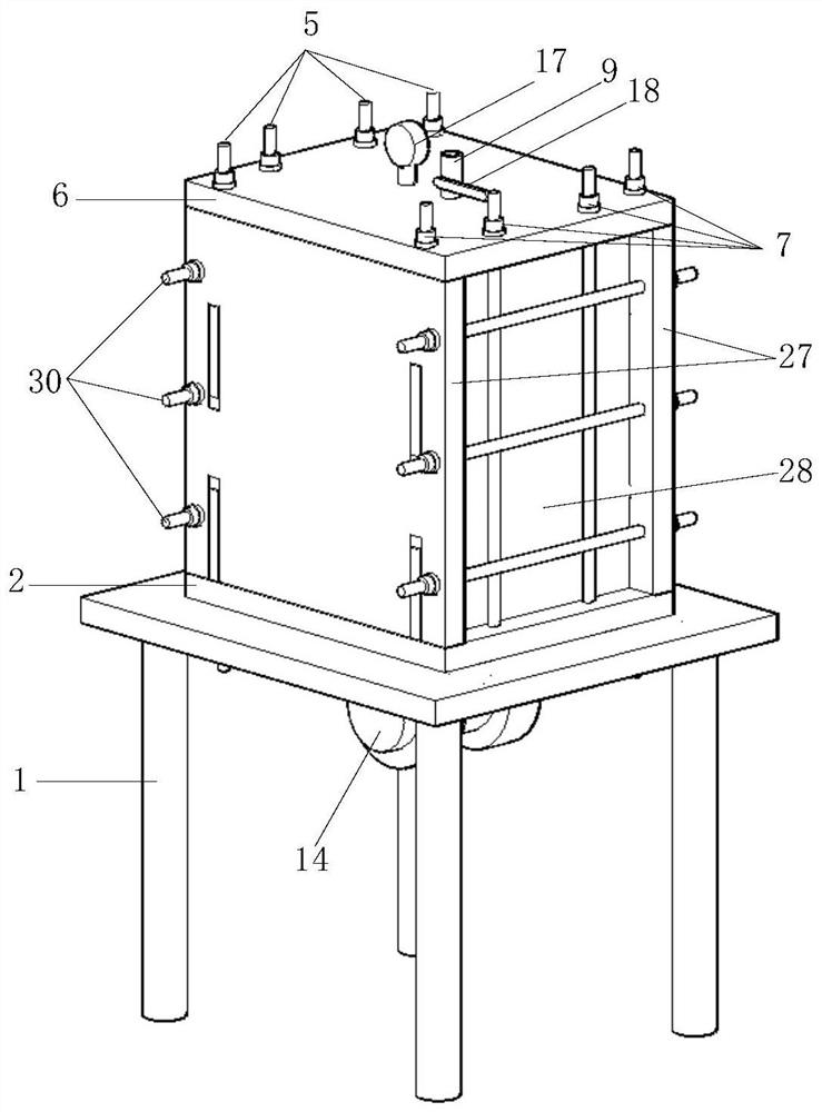
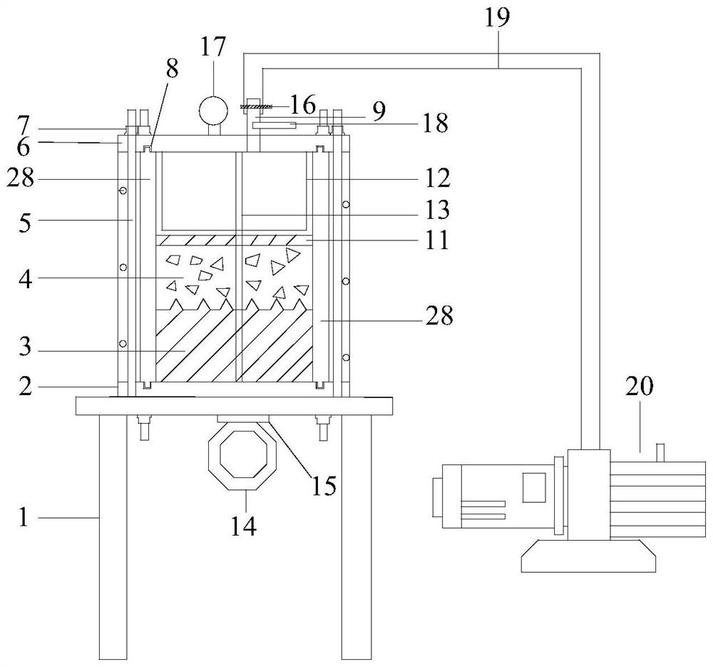
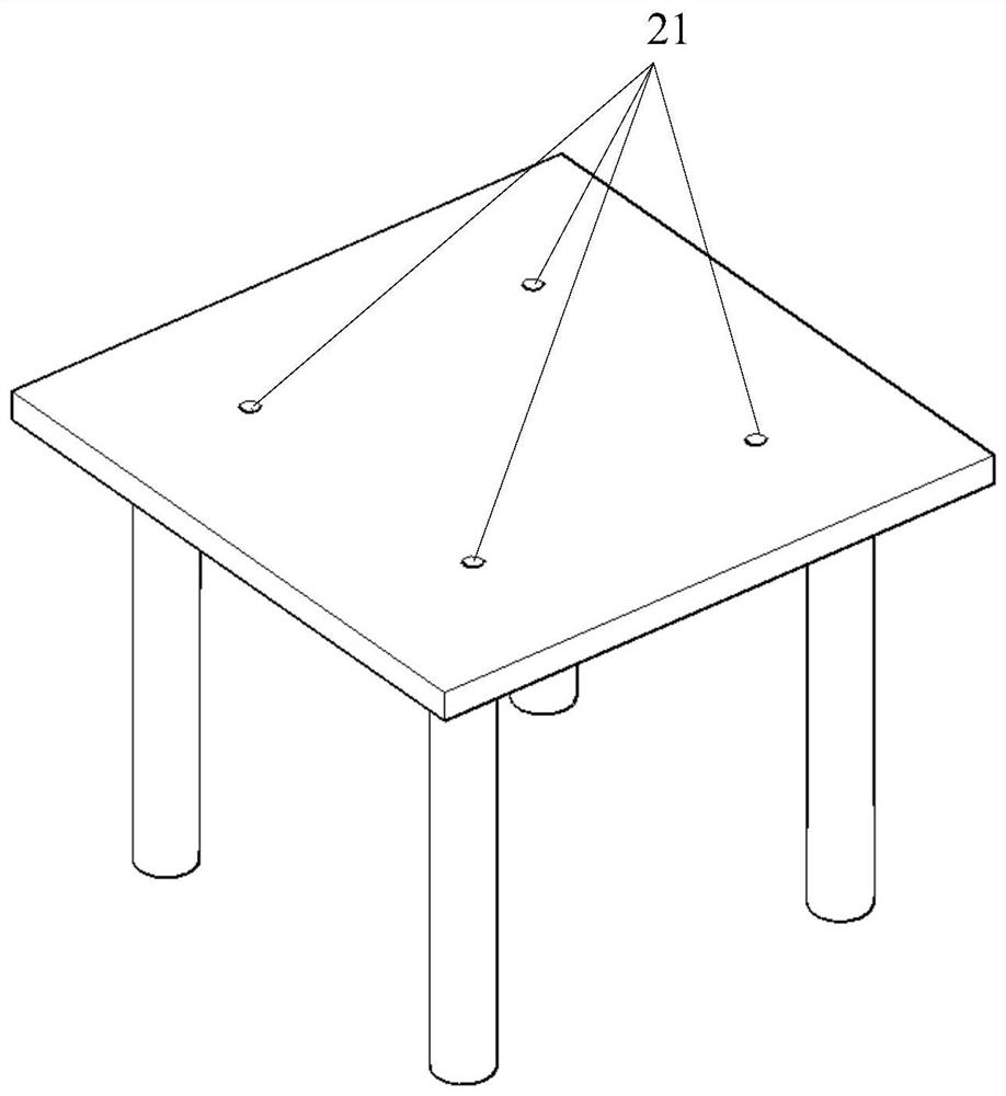
[0037] see Figure 1 to Figure 3 , the present embodiment provides a device for preparing a pile-rock interface compression shear sample, including a working platform 1, a flat-plate attached vibrator 14, a base 2, A steel formwork 27, B steel formwork 28, and a sealing cover 6. The air compressor 20 and the air pipeline 19, the base 2 and the sealing cover 6 are provided with four grooves 22 and eight fixing holes 21, the grooves 22 are embedded with a sealing strip 8, the The bottom of the A steel formwork 27 and the B steel formwork 28 and the raised parts 10 at the top are all embedded in the inside of the groove 22, and the working platform 1, the base 2, the A steel formwork 27, the B steel formwork 28 and the sealing cover 6 pass through The horizontal fixing rod 30 an...


PUM


Abstract

The invention discloses a device for preparing a pile-rock interface compression-shear sample and a test method, relates to the technical field of rock-socketed pile-rock contact surfaces in geotechnical engineering, and mainly aims at solving the problem that an existing device for preparing the pile-rock interface compression-shear sample is large in error. The device comprises a working platform, a flat plate type attached vibrator, a base, a steel template A, a steel template B, a sealing cover, an air compressor and an air conveying pipeline. The base and the sealing cover are each provided with four grooves and eight fixing holes. Sealing strips are embedded in the grooves, and the protruding parts of the bottoms and the tops of the A steel formwork and the B steel formwork are embedded into the grooves. The working platform, the base, the steel formwork A, the steel formwork B and the sealing cover are combined and connected through the transverse fixing rods and the vertical fixing rods, so that the sealing performance is good, operation is easy, operation links are reduced, and more accurate results can be obtained easily.

Description

technical field [0001] The invention relates to the technical field of rock-socketed pile pile-rock contact surfaces in geotechnical engineering, in particular to a device and a use method for preparing pile-rock interface compression-shear samples. Background technique [0002] The indoor compression-shear test of structural surfaces is a widely used test. At present, during the preparation of many pile-rock interface compression shear samples, the rock samples obtained on site are directly poured in the model box. [0003] However, this method of preparing pile-rock interface compression-shear samples does not consider the roughness of the pile-rock interface at different pile depths and the penetration of concrete to the surrounding rock under a certain grouting pressure, because the geological conditions are complex. For rock-socketed piles that bear heavy loads and have deep rock-socketed depths, due to differences in the geometry of the construction interface, pile fo...

Claims


Application Information

Patent Timeline
Patent Type & Authority Applications(China)
IPC IPC(8): G01N1/28G01N3/02G01N3/62
CPCG01N1/28G01N3/02G01N3/62
Inventor 张振华张丹余跃程奚邦禄徐国娟殷永高
Owner HEFEI UNIV OF TECH
Why Eureka
Try Eureka