Method for calculating influence line of equal-span and equal-section continuous beam

A calculation method and constant-section technology, applied in the field of structural analysis, can solve the problems of inconvenient application, difficult to obtain the change law of continuous beam deformation internal force, and many steps.

Active Publication Date: 2021-01-29
UNIV OF SCI & TECH BEIJING
View PDF8 Cites 0 Cited by
  • Summary
  • Abstract
  • Description
  • Claims
  • Application Information

AI Technical Summary

Problems solved by technology

The above methods have their own characteristics and pertinence, but for the calculation of continuous beams with equal span and equal cross-section, there are many steps and it is inconvenient to apply
More importantly, the existing methods are only applicable to continuous beams with a sp

Method used


Image

  • Method for calculating influence line of equal-span and equal-section continuous beam
  • Method for calculating influence line of equal-span and equal-section continuous beam
  • Method for calculating influence line of equal-span and equal-section continuous beam

Examples


Embodiment 1

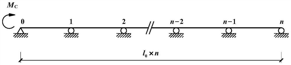
[0264] Assuming a 3-span continuous beam, each span is l 0 , the bending stiffness EI of the main beam along the length direction is constant. It is necessary to determine the bending moment influence line equation of the mid-span section.

[0265] From the above conditions, it can be seen that the number of spans is n=3, and the cross-section of the middle span is located at y=(1+1 / 2)l 0 Therefore, r=1, λ=1 / 2. Find the constants separately According to these results, the bending moment influence line M of the mid-span section can be obtained by formula (29) 1+1 / 2 (x) is:

[0266]

Embodiment 2

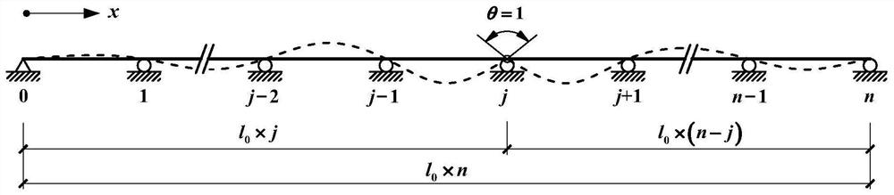
[0268] Assuming that the number of spans of a continuous girder bridge is n, find the nodal rotation angle and bending moment when the following three loads act on span u: (1) Uniformly distributed load q (q is positive downward); (2) Mid-span Concentrated force F (F is positive downward); (3) The temperature difference ΔT between the top and bottom surfaces acts (when the temperature of the top surface is greater than that of the bottom surface, ΔT is positive).

[0269] According to structural mechanics, the fixed end bending moments corresponding to the above three loads all satisfy conditions, and are equal to where α and h are the coefficient of linear expansion of the material and the section height, respectively. the above Substituting into formula (50) and formula (51), the rotation angle z of n-span continuous girder bridge can be obtained j and bending moment M j . From the expressions of (50) and (51), it can be seen that under the action of the uniform load...


PUM


Abstract

The invention provides a method for calculating an influence line of an equal-span and equal-section continuous beam, and belongs to the technical field of structural analysis. The method comprises the following steps: firstly, determining a solution of the multi-span continuous beam under the action of concentrated bending moment at the leftmost beam end, then determining a solution of the multi-span continuous beam under the action of concentrated bending moment at the rightmost beam end according to a mirror image relationship, determining the beam end rotating rigidity of the multi-span continuous beam, and determining a node bending moment influence line of the multi-span continuous beam according to a work reciprocity theorem; finally, determining analytical formulas of other influence lines. According to the method, for uniform-section continuous beams with equal spans and any span number, by introducing the beam end rotating rigidity of multi-span beams, an influence line analytical formula of structural internal force, displacement and support counterforce and a general calculation formula of continuous beam structure response are derived. The formula belongs to an accurate solution, calculation is convenient, universality is high, and parameter analysis is facilitated; the limit value of structural response can be given when the span number of the continuous beam tends to be infinite, and the mechanical property of the continuous beam is revealed in a panoramic mode.

Description

technical field [0001] The invention relates to the technical field of structural analysis, in particular to a calculation method for influence lines of continuous beams of equal span and equal section. Background technique [0002] Continuous beams are widely used in construction, bridges, pipelines and other projects. Although there are various forms of continuous beams, the most classic structural form is still continuous beams of equal span and constant section, and its solution method has been extensively studied. In addition to the finite element analysis method, the theoretical solution methods include the classic force method (based on the three-moment equation), displacement method, moment distribution method, cubic spline beam function method, direct writing method, finite difference method, equal straight beam replacement method, Segmented independent integrated integral method, distributed transfer function method, etc. The above methods have their own characte...

Claims


Application Information

Patent Timeline
IPC IPC(8): G06F30/13G06F119/14
CPCG06F30/13G06F2119/14
Inventor 周毅
Owner UNIV OF SCI & TECH BEIJING
Why Eureka
Try Eureka