A device for actively controlling trailing edge winglets with large forward ratio rotor blade anti-stall

A technology of rotor blades and active control, applied in the field of helicopter rotors, can solve the problems of inability to adapt to high-speed helicopters, increased resistance of backward blades, and reduced cruising efficiency, and achieves the effect of alleviating the aerodynamic problem of reverse flow and controlling the reverse flow speed.

Active Publication Date: 2021-12-07
LOW SPEED AERODYNAMIC INST OF CHINESE AERODYNAMIC RES & DEV CENT
View PDF20 Cites 0 Cited by
  • Summary
  • Abstract
  • Description
  • Claims
  • Application Information

AI Technical Summary

Problems solved by technology

Such airflow is easy to generate separation, resulting in a sharp increase in the resistance of the backward blades and a significant reduction in cruise efficiency
The airfoil has not been specially designed for the flow characteristics of the rotor reflux area, and cannot meet the needs of high-speed helicopters; therefore, there is an urgent need for a large forward ratio rotor blade reflux that can control the reverse stall and is suitable for high-speed helicopters. Actively Controlled Trailing Edge Winglets

Method used


Image

  • A device for actively controlling trailing edge winglets with large forward ratio rotor blade anti-stall
  • A device for actively controlling trailing edge winglets with large forward ratio rotor blade anti-stall
  • A device for actively controlling trailing edge winglets with large forward ratio rotor blade anti-stall

Examples


Embodiment 1

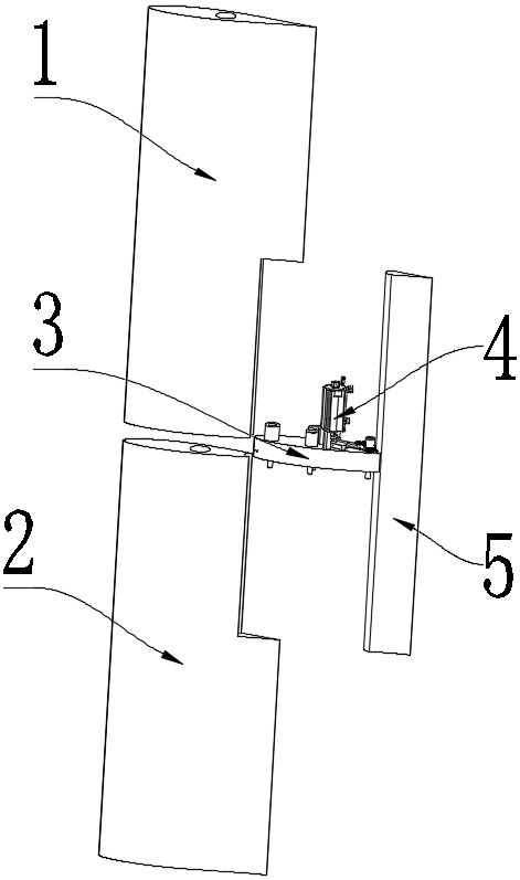
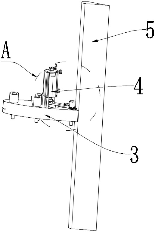
[0025] Example 1: See Figure 1 to Figure 4 , a large forward ratio rotor blade anti-stall active control trailing edge winglet device of the present embodiment comprises a main rotor and an anti-arc winglet 5 arranged on the trailing edge of the main rotor, and a transmission device 4 arranged inside the main rotor , the transmission device 4 is used to drive the anti-arc winglet 5 to do sinusoidal oscillating motion; the main rotor includes a motor 41, an eccentric wheel, a reciprocating slider 44 and a transmission gear set, and the motor 41 drives the eccentric wheel to rotate, and then drives the reciprocating slider 44 to make a straight line Reciprocating motion, the end of the reciprocating slider 44 away from the eccentric wheel is provided with a rack, the rack is engaged with the transmission gear set, the anti-arc winglet 5 is provided with a winglet gear 47 engaged with the transmission gear set, and the rack drives the transmission gear set Rotate, and then drive...

Embodiment 2

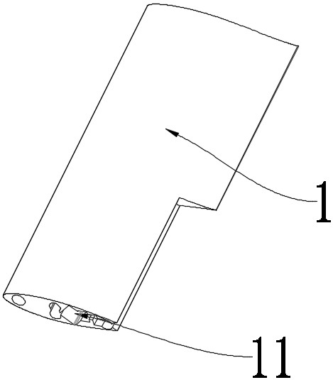
[0026] Embodiment 2: The transmission device 4 of this embodiment is arranged inside the main rotor. The main rotor includes a detachably connected first end portion 1 and a first clamping portion 3. The first clamping portion 3 is close to the first end portion 1. One side is provided with a reciprocating slide rail 43 for the reciprocating slider 44 to move, and the side of the first end 1 close to the first engaging part 3 is provided with an accommodating cavity 11 for accommodating the transmission device 4 . In this embodiment, the side of the first engaging portion 3 away from the first end portion 1 is provided with a second end portion 2 , and the second end portion 2 , the first end portion 1 and the first engaging portion 3 are detachably connected. In this embodiment, a plurality of first fixing holes are provided on the first clamping part 3, and a plurality of second fixing holes are provided on the first end part 1 corresponding to the first fixing holes, and a p...

Embodiment 3

[0027]Embodiment 3: The eccentric wheel of this embodiment includes an eccentric pin and a flange 42, the center of the flange 42 is provided with a rotating hole for connecting the output shaft of the motor 41, and the flange 42 is provided with a rotating hole around the rotating hole for inserting The eccentric pins are connected to a plurality of positioning holes, and the eccentric pins are clamped on the reciprocating slider 44. One end of the reciprocating slider 44 connected to the eccentric pin in this embodiment is provided with a second clamping part, and a transverse groove is arranged on the second clamping part, and the width of the transverse groove is slightly larger than the diameter of the eccentric pin to accommodate the eccentric pin. The pin slides in the groove, driving the reciprocating slider 44 to reciprocate.


PUM


Abstract

The invention discloses a device for actively controlling the trailing edge winglet of a large forward ratio rotor blade anti-stall, which comprises a main rotor and a reverse arc winglet arranged on the trailing edge of the main rotor. Drive the anti-arc winglet to do sinusoidal oscillation motion; the transmission device includes motor, eccentric wheel, reciprocating slider and transmission gear set, the motor drives the eccentric wheel to rotate, and then drives the reciprocating slider to do linear reciprocating motion, and the reciprocating slider is far away from the end of the eccentric wheel A rack is provided, and the rack is meshed with the transmission gear set, and a winglet gear meshed with the transmission gear set is arranged in the anti-arc winglet, and the rack drives the transmission gear set to rotate, and then drives the winglet gear to rotate. The anti-arc winglet performs sinusoidal oscillation motion on the trailing edge of the main rotor, and bends the trailing edge through the deformation of the curved surface, so that the trailing edge of the airfoil can be more closely aligned with the oncoming airflow, thereby greatly alleviating the aerodynamic problem of reverse flow, and then controlling the reverse flow. drain rate.

Description

technical field [0001] The invention relates to the field of helicopter rotors, in particular to a device for actively controlling trailing edge winglets with a large forward ratio rotor blade anti-stall. Background technique [0002] When the helicopter is flying forward with a certain forward ratio μ, due to the superimposed effect with the incoming flow, the relative airflow velocities between the forward blade area and the backward blade area of ​​the rotor are asymmetric. In the backward blade area, the relative radius r is less than μR|sinψ| a section of the blade, there will be a phenomenon that the relative airflow blows from the trailing edge to the front edge, and the area where this phenomenon exists is called the "reflux zone"; in the reverse flow zone The aerodynamic efficiency of the inner blade is low, there is a serious flow separation phenomenon, and it is prone to stall. There are obvious differences in the angle of attack, lift, drag, and pitching moment c...

Claims


Application Information

Patent Timeline
Patent Type & Authority Patents(China)
IPC IPC(8): B64C27/467
Inventor 姜裕标李国强杨永东车兵辉覃晨
Owner LOW SPEED AERODYNAMIC INST OF CHINESE AERODYNAMIC RES & DEV CENT
Why Eureka
Try Eureka