Leg recovery nursing training device for community nursing
A training device and leg technology, applied in physical therapy, passive exercise equipment, etc., can solve problems such as high disability rate, affecting patient's quality of life, patient's labor capacity, and fatigue
- Summary
- Abstract
- Description
- Claims
- Application Information
AI Technical Summary
Problems solved by technology
Method used
Image
Examples
Embodiment 1
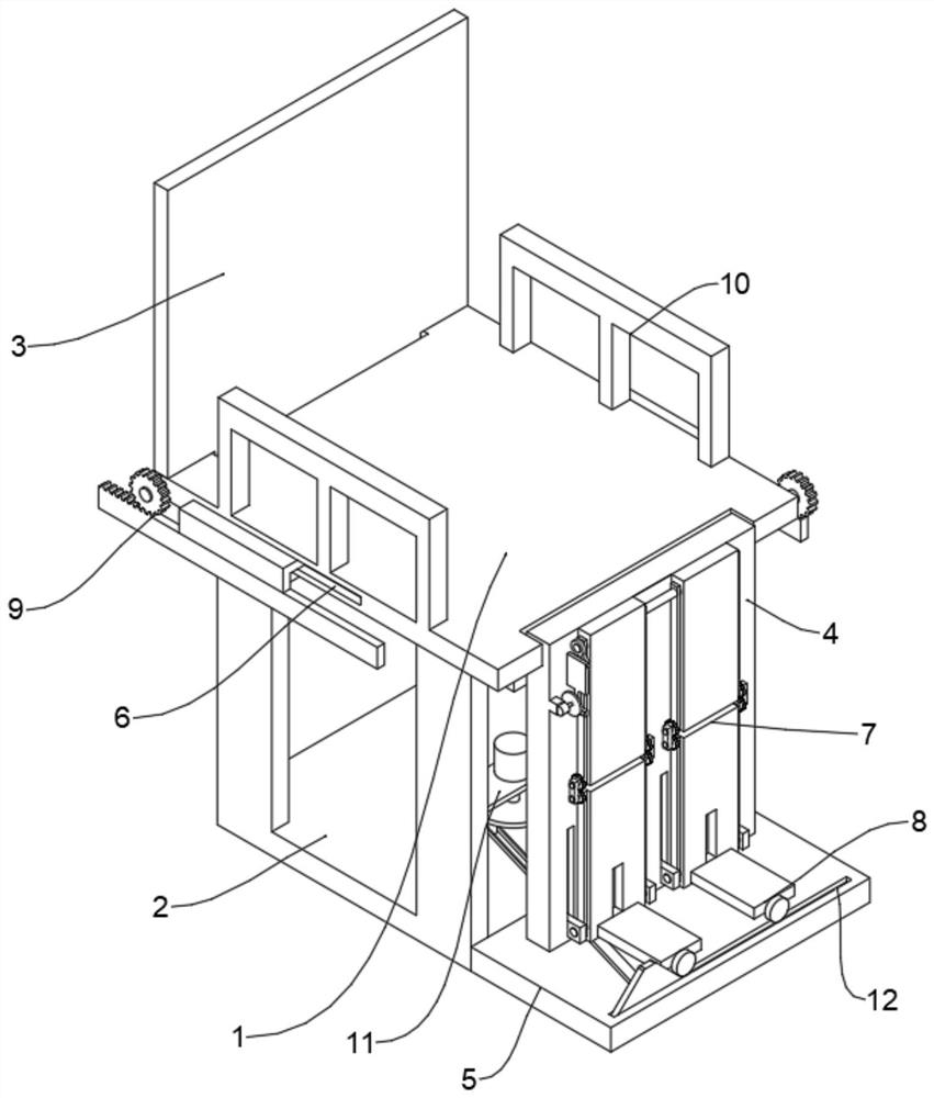
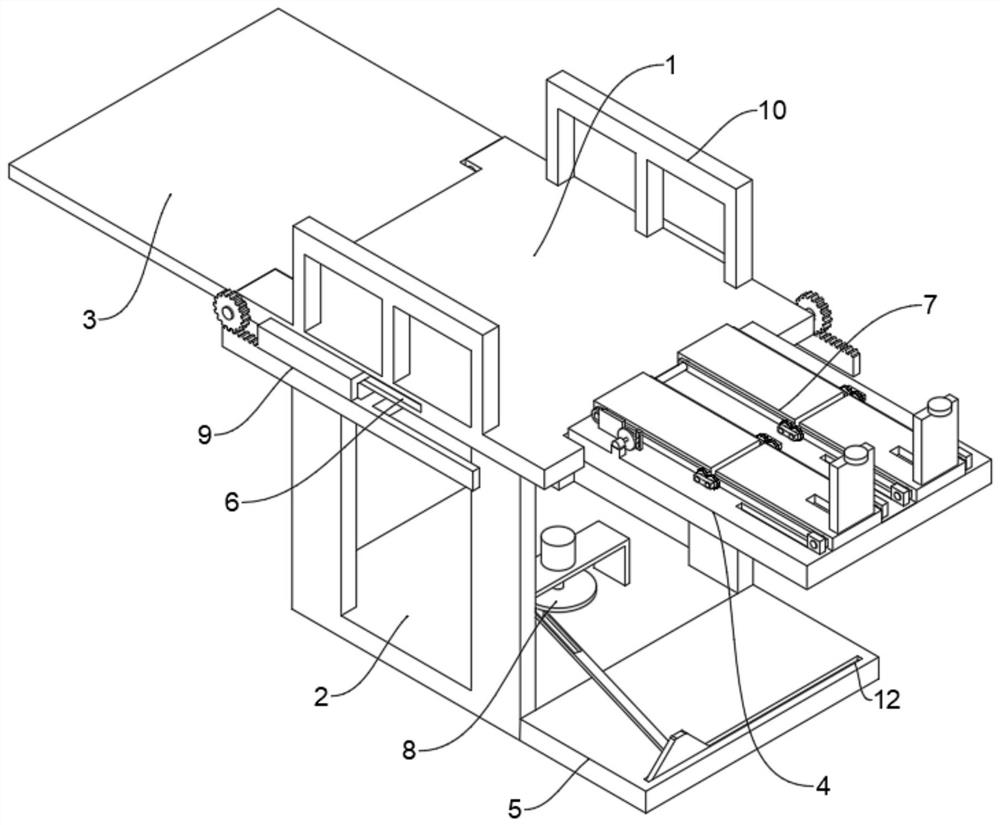
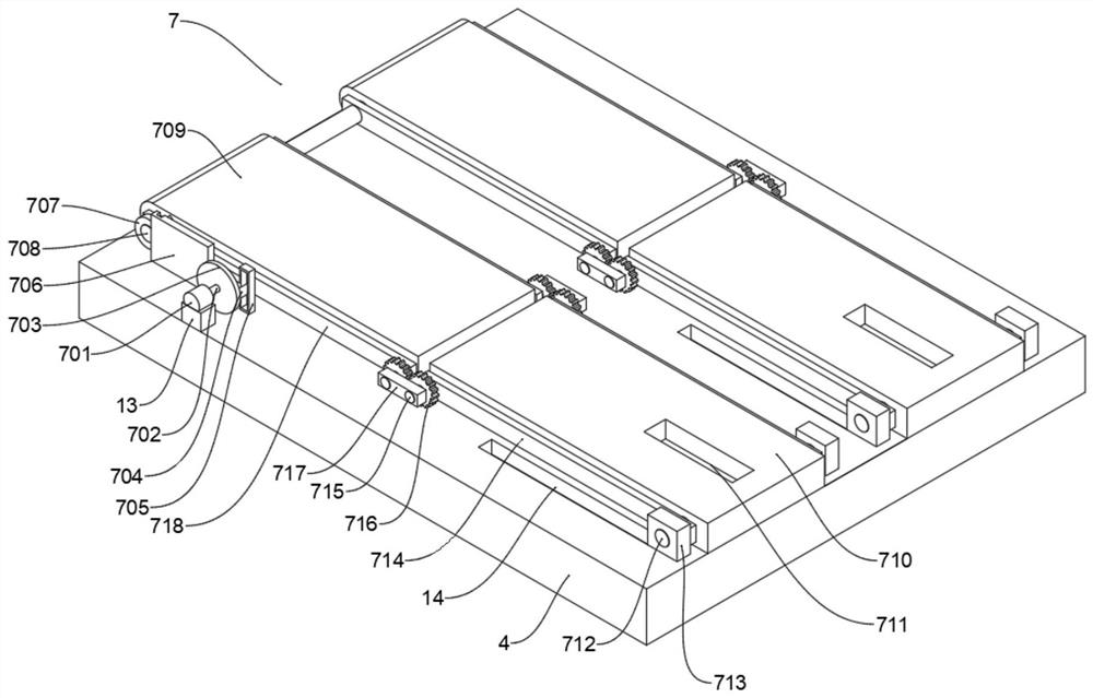
[0028] Such as Figure 1-4 As shown, a community nursing leg recovery nursing training device includes a seat plate 1, guardrails 10 are fixedly installed on both sides of the top of the seat plate 1, first chute 6 is provided on both sides of the seat plate 1, and the seat plate 1 A support frame 2 is fixedly installed at the bottom, a support frame 11 is fixedly installed at the top of the support frame 2, a base plate 5 is fixedly installed at the front end of the support frame 2, a second chute 12 is provided on one side of the top of the base plate 5, and a front end is fixedly installed at the front end of the seat plate 1. Board 4, the rear end of the seat board 1 is fixed with a backing board 3, the front board 4 is provided with a knee joint nursing mechanism 7, a rotating mechanism 9 is connected between the front board 4 and the backing board 3, and a reciprocating mechanism is installed on the support frame 2 8. Several grooves 14 are opened on the front plate 4, a...
Embodiment 2
[0035] Such as Figure 5 As shown, the reciprocating mechanism 8 includes a second driving device 801, the second driving device 801 is fixedly installed on the support frame 11, the output ends of the second driving device 801 are fixedly connected with the second connecting shaft 802, and the second connecting shaft 802 runs through the The support frame 11 is rotatably connected with the support frame 11, the second connecting shaft 802 is fixedly equipped with a second disk 803, and the second disk 803 is fixedly installed with a third sliding column 804, and the bottom of the third sliding column 804 is arranged There is a linkage plate 805, and a through groove 806 is opened on the linkage plate 805. The third sliding column 804 is slidably connected with the linkage plate 805 through the through groove 806. A support column 807 is arranged on one side of the linkage plate 805, and the linkage plate 805 passes through the through groove 806 and the linkage plate 805. The...
Embodiment 3
[0038] Such as Image 6 As shown, the rotating mechanism 9 includes a cylinder 901, the cylinder 901 is fixedly installed on the bottom of the seat plate 1, a piston rod 902 is fixedly connected to the cylinder 901, a horizontal plate 903 is fixedly installed on the piston rod 902, and side plates 903 are fixedly installed on both sides of the horizontal plate 903. Plate 904, the top of side plate 904 is all fixedly installed with connecting frame 905, and connecting frame 905 is all slidably connected in the first chute 6, and side plate 904 one end is all fixedly installed with several tooth racks 906, and tooth bar 906 all meshes and connects with The connecting gear 907 is fixedly equipped with a second rotating shaft 908 on the connecting gear 907, and the second rotating shaft 908 is connected to both ends of the seat plate 1 in rotation, and the second rotating shaft 908 is fixedly installed on the back plate 3 and the front plate 4 respectively.
[0039] The rotary mec...
PUM
 Abstract
Description
Claims
Application Information
 - R&D
- Intellectual Property
- Life Sciences
- Materials
- Tech Scout
- Unparalleled Data Quality
- Higher Quality Content
- 60% Fewer Hallucinations
Browse by: Latest US Patents, China's latest patents, Technical Efficacy Thesaurus, Application Domain, Technology Topic, Popular Technical Reports.
© 2025 PatSnap. All rights reserved.Legal|Privacy policy|Modern Slavery Act Transparency Statement|Sitemap|About US| Contact US: help@patsnap.com


