
Ring main unit state monitoring method

A ring network cabinet and state technology, applied in the field of ring network cabinet monitoring, can solve the problems of different installation locations and inability to manually inspect, and achieve the effect of guaranteeing electricity demand and safe and reliable state monitoring means

Active Publication Date: 2021-11-26
NANJING BOLU ELECTRIC CO LTD
View PDF1 Cites 0 Cited by
  • Summary
  • Abstract
  • Description
  • Claims
  • Application Information

AI Technical Summary

Problems solved by technology

[0005] The embodiment of the present invention provides a state monitoring method for ring network cabinets, which can solve the problem that manual inspection cannot be performed efficiently due to the large number of ring network cabinets, different installation positions, and fully enclosed structure

Method used


Image

  • Ring main unit state monitoring method
  • Ring main unit state monitoring method
  • Ring main unit state monitoring method

Examples


Embodiment Construction

[0022] In order to make the purpose, technical solutions and advantages of the embodiments of the present invention clearer, the technical solutions in the embodiments of the present invention will be clearly and completely described below in conjunction with the drawings in the embodiments of the present invention. Obviously, the described embodiments It is only some embodiments of the present invention, but not all embodiments. Based on the embodiments of the present invention, all other embodiments obtained by persons of ordinary skill in the art without making creative efforts belong to the protection scope of the present invention.

[0023] The terms "first", "second", "third", "fourth", etc. (if any) in the description and claims of the present invention and the above drawings are used to distinguish similar objects and not necessarily Describe a specific order or sequence. It is to be understood that the data so used are interchangeable under appropriate circumstances ...


PUM


Abstract

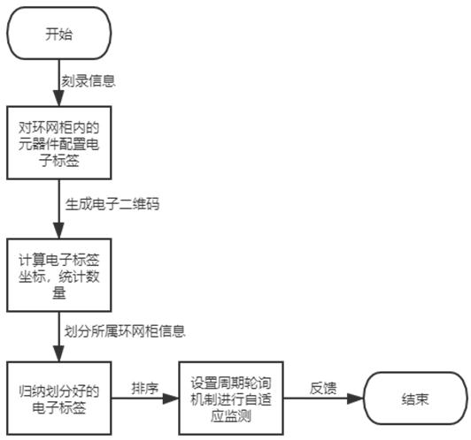
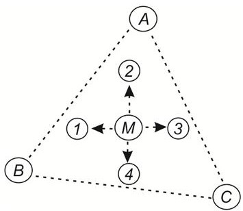
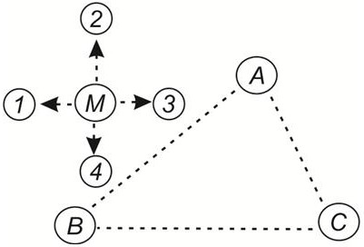
The invention provides a ring main unit state monitoring method which comprises the following steps of configuring electronic tags for the components in ring main units, and transmitting and storing the state data information and the position information of the components of the ring main units by using the electronic tags; calculating the position coordinates of the electronic tags based on an APIT algorithm, and summarizing and dividing the number of the electronic tags and the information of the ring main units to which the electronic tags belong; placing the electronic tags belonging to the same ring main unit in the same candidate space, and sequentially arranging the electronic tags with different coordinates in the candidate space according to the recorded component information; and setting a periodic polling mechanism, carrying out self-adaptive monitoring on the state data of the ring main units on the electronic tags regularly, and sending a monitoring result to the background of a power grid monitoring center for management and control. The invention provides a high-efficiency and more reliable ring main unit state monitoring means for the ring main units which are of totally-closed structures and cannot be inspected manually so as to guarantee the electricity demands and the safety.

Description

technical field [0001] The invention relates to the technical field of ring network cabinet monitoring, in particular to a state monitoring method of a ring network cabinet. Background technique [0002] In recent years, the construction of smart grid has been highly valued and has achieved considerable development. The intelligence and informatization of power transmission and transformation systems have developed to a certain level. The ring main unit (or distribution transformer) is located at the end of the distribution network and is used for It is self-evident that the 10kV high-voltage power delivered by the substation is converted into 0.4kV lighting power and power power for residents, so the importance of ensuring its effective operation is self-evident. [0003] However, at present, the intelligent monitoring construction of ring network cabinets is obviously lagging behind. The main reason is that the number of ring network cabinets is large, the installation loc...

Claims


Application Information

Patent Timeline
Patent Type & Authority Applications(China)
IPC IPC(8): G06K17/00G06Q50/06G16Y10/35G16Y20/10G16Y20/20G16Y40/10G16Y40/50
CPCG06K17/0029G06Q50/06G16Y10/35G16Y20/10G16Y20/20G16Y40/10G16Y40/50
Inventor 鲍卫滕林峰刘伟
Owner NANJING BOLU ELECTRIC CO LTD
Learn More