Decorative garden fountain with loudspeaker
A decorative, loudspeaker technology, applied in the direction of loudspeaker transducer fixing, spraying device, liquid spraying device, etc., can solve the problem of limited function of decorative garden fountains
- Summary
- Abstract
- Description
- Claims
- Application Information
AI Technical Summary
Problems solved by technology
Method used
Image

Examples
Embodiment Construction
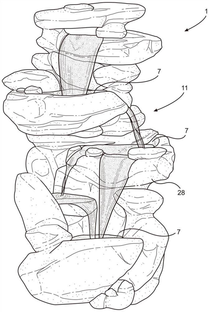
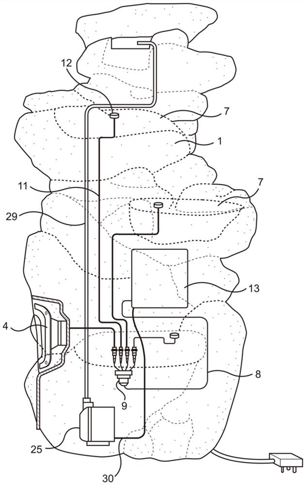
[0020] There is provided a portable decorative fountain comprising: a) a portable body having one or more cavities for collecting water; b) a pump for pumping water in an upward direction from at least one cavity; c ) a conduit for carrying the water pumped by the pump; and d) a speaker connected to the main body to play sound. The speaker is usually placed inside the body, which has openings for conducting sound.
[0021] A decorative fountain 1 with a loudspeaker 4 is provided. Fountain 1 may have multiple speakers, for example 1, 2, 3, 4, or 5. The decorative fountain 1 can be adapted to be placed in a garden. The decorative fountain 1 may have one or more components including a body / housing 28, a cavity 7 (in the form of a pool as shown) for collecting water, a pump 25 and a pump 25 for moving the water by the force generated by the pump 25. Conduit 29 moving upwards from the lowest chamber 7 .
[0022] The fountain 1 may have one or more cavities 7 (pools), for exampl...
PUM
| Property | Measurement | Unit |
|---|---|---|
| Weight | aaaaa | aaaaa |
Abstract
Description
Claims
Application Information