Multi-speaker audio system and automatic control method

a multi-speaker audio system and automatic control technology, applied in the direction of stereophonic arrangments, pseudo-stereo systems, loudspeaker enclosure positioning, etc., can solve the problems of inconvenient user experience, neither increase the number of speakers, nor rearrange, and it is difficult for a listener to enter accurate speaker layout information in the audio system

Inactive Publication Date: 2010-03-09
SONY CORP
View PDF2 Cites 317 Cited by
  • Summary
  • Abstract
  • Description
  • Claims
  • Application Information

AI Technical Summary

Problems solved by technology

This arrangement inconveniences the user, because the user can neither increase the number of speakers, nor rearrange the layout of the speaker device to any desired one.
However, it is difficult for a listener to enter accurate speaker layout information in the audio system.
This inconveniences the user.

Method used


Image

  • Multi-speaker audio system and automatic control method
  • Multi-speaker audio system and automatic control method
  • Multi-speaker audio system and automatic control method

Examples


first embodiment

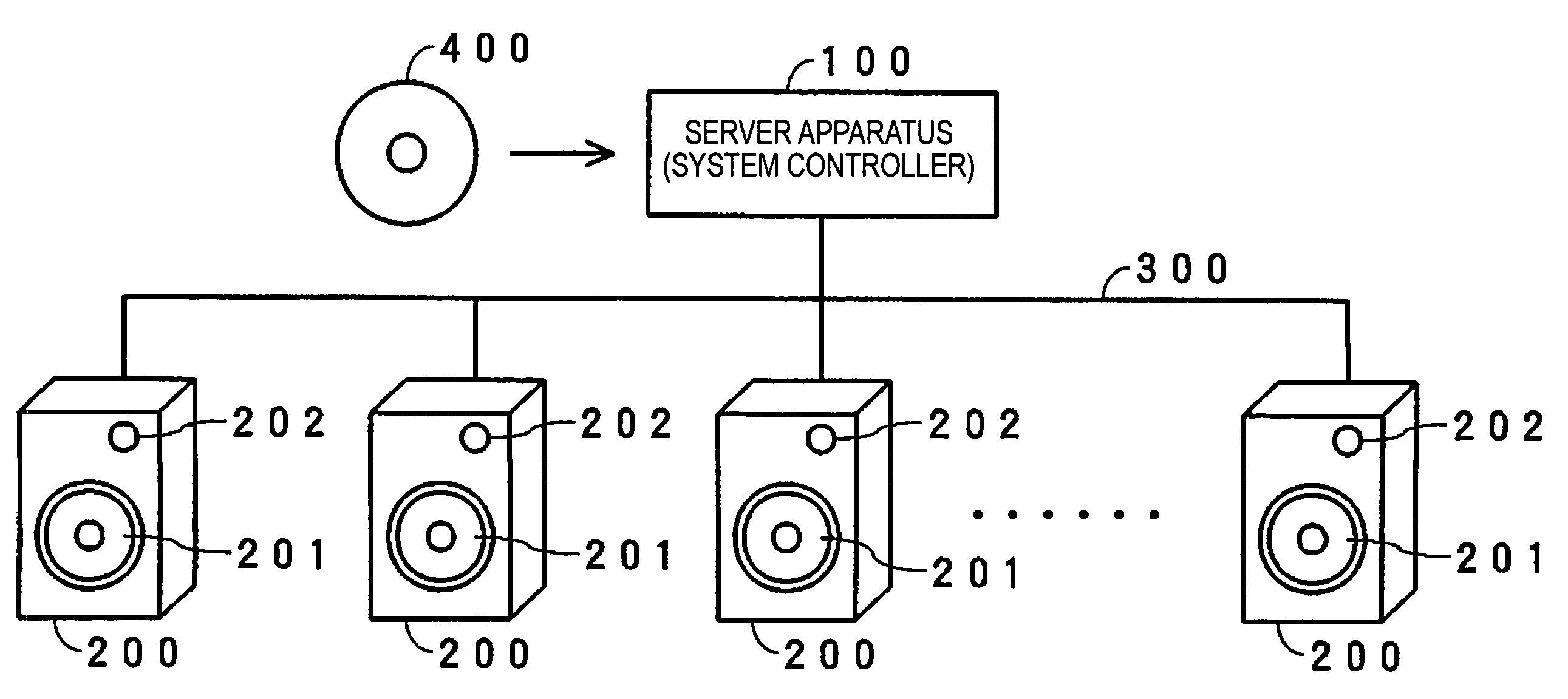
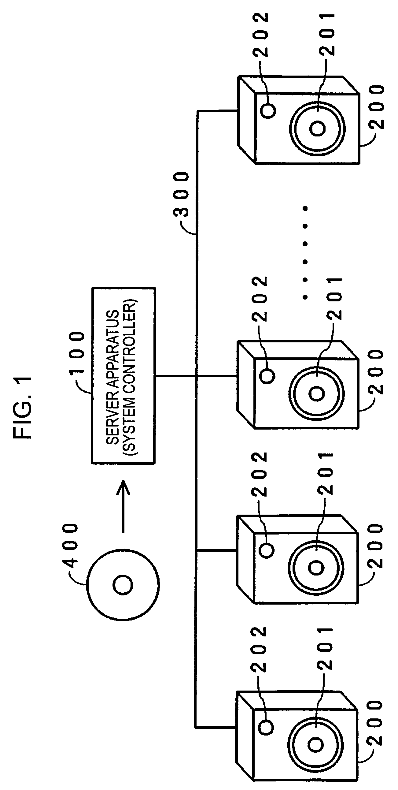
[0119]FIG. 1 is a system configuration of an audio system in accordance with a first embodiment of the present invention. The audio system of the first embodiment includes a server apparatus 100, a plurality of speaker devices 200 connected thereto via a common transmission line, such as a serial bus 300. In the discussion that follows, an identification (ID) number is used to identify each speaker device.

[0120]The bus 300 can be one of a universal serial bus (USB) connection, an IEEE (Institute Electrical and Electronics Engineers) 1394 Standard connection, an MID (musical instrument digital interface) connection, or equivalent connection.

[0121]The server apparatus 100 replays, from the 5.1-channel surround signals recorded in the disk 400, the multi-channel audio signals of the L-channel, the R-channel, the center channel, the LS channel, the RS channel, and the LFE-channel are properly localized with reference to a listener.

[0122]The server apparatus 100 of the first embodiment h...

second embodiment

[0333]FIG. 27 is a block diagram illustrating the entire structure of an audio system in accordance with a second embodiment of the present invention. In the second embodiment, a system controller 600, separate from the server apparatus 100, and the plurality of speaker devices 200, are connected to each other via the bus 300.

[0334]In the second embodiment, the server apparatus 100 has no function for generating each speaker signal from a multi-channel audio signal. Each speaker device 200 has a function for generating a speaker signal therefor.

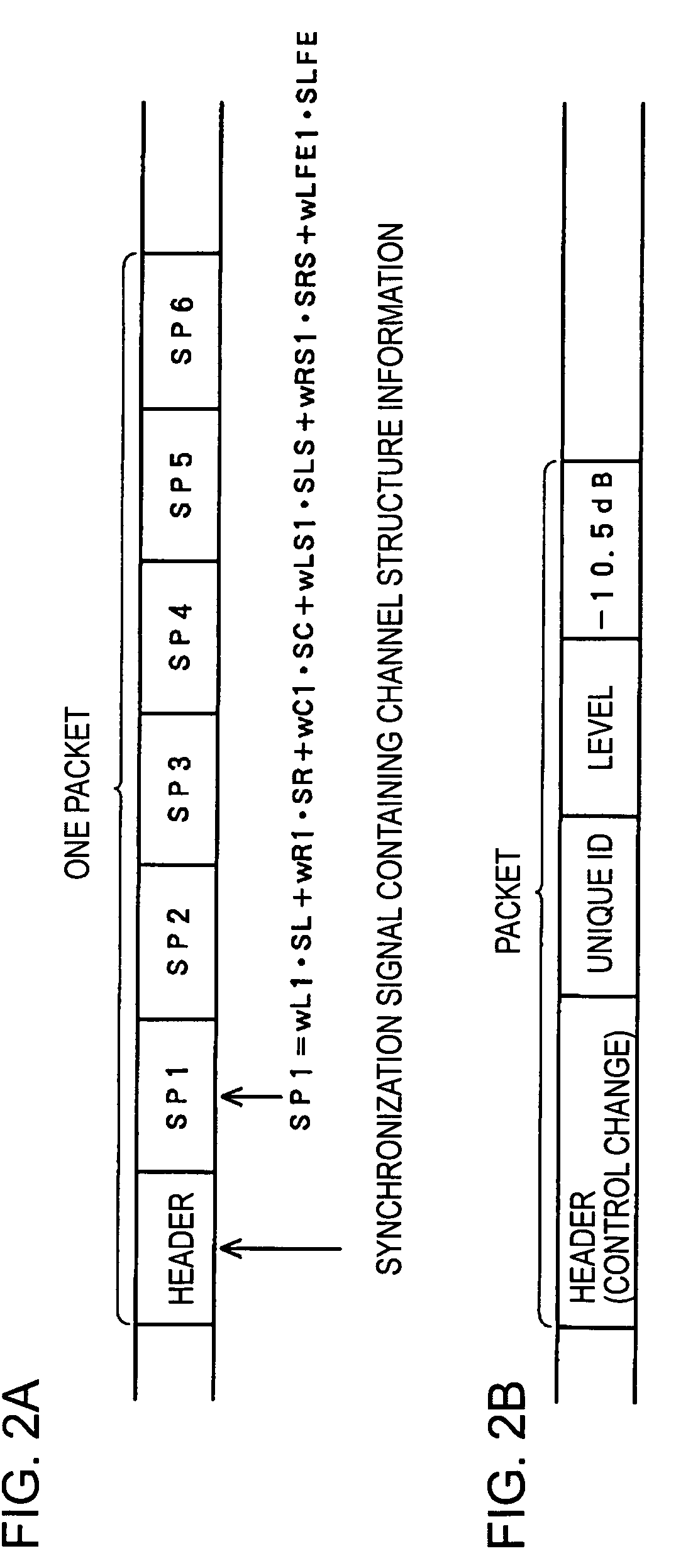
[0335]The server apparatus 100 transmits, via the bus 300, audio data in the form of a packet in which a multi-channel audio signal is packetized every predetermined period of time. The audio data as the 5.1-channel surround signal transmitted from the server apparatus 100 contains, in one packet, an L-channel signal, an R-channel signal, a center-channel signal, an LS-channel signal, an RS-channel signal, and an LFE-channel signal as shown i...

third embodiment

[0353]As the audio system of the first embodiment of FIG. 1, an audio system of a third embodiment of the present invention includes the server apparatus 100 and the plurality of speaker devices 200 connected to the server apparatus 100 via the bus 300. Each of the speaker devices 200 has the functions of the system controller 600.

[0354]As in the second embodiment, the server apparatus 100 in the third embodiment has no function for generating each speaker signal from a multi-channel audio signal. Each speaker device 200 has a function for generating a speaker signal therefor. The server apparatus 100 transmits, via the bus 300, audio data in the form of a packet in which a multi-channel audio signal is packetized every predetermined period of time as shown in FIG. 28A. In the third embodiment, the packet for control change of FIG. 28B is effective.

[0355]Each speaker device 200 buffers one-packet information transmitted from the server apparatus 100 in the RAM thereof, generates a s...


PUM


Abstract

A sound produced at the location of a listener is captured by a microphone in each of a plurality of speaker devices. A sever apparatus receives an audio signal of the captured sound from all speaker devices, and calculates a distance difference between the distance of the location of the listener to the speaker device closest to the listener and the distance of the listener to each of the plurality of speaker devices. When one of the speaker devices emits a sound, the server apparatus receives an audio signal of the sound captured by and transmitted from each of the other speaker devices. The server apparatus calculates a speaker-to-speaker distance between the speaker device that has emitted the sound and each of the other speaker devices. The server apparatus calculates a layout configuration of the plurality of speaker devices based on the distance difference and the speaker-to-speaker distance.

Description

BACKGROUND OF THE INVENTION[0001]1. Field of the Invention[0002]The present invention relates to a server apparatus, a speaker device and a multi-speaker audio system. The present invention also relates to a layout configuration detection method of the speaker devices in the multi-speaker audio system.[0003]2. Description of the Related Art[0004]FIG. 61 shows a typical audio system in which a multi-channel acoustic field of a multi-channel signal such as 5.1-channel surround signal is produced using a plurality of speaker devices.[0005]The audio system includes a multi-channel amplifier 1 and a plurality of speaker devices 2 of the number equal to the number of channels. The 5.1-channel surround signals include signals of a left (L) channel, a right (R) channel, a center channel, a left-surround (LS) channel, a right-surround (RS) channel, and a low-frequency effect (LFE) channel. If all channels are used for playing, six speakers are required. The six speakers are arranged with res...

Claims


Application Information

Patent Timeline
Patent Type & Authority Patents(United States)
IPC IPC(8): H04R29/00H04R5/02H04S5/02H04R3/12H04S7/00
CPCH04S7/302H04R2205/024
Inventor SASAKI, TORUITABASHI, TETSUNORI
Owner SONY CORP
Why Eureka
Try Eureka