Compensating filters

a filter and compensation technology, applied in the field of filtering audio signals, can solve the problems of inability to measure the response of the loudspeaker separately in practice, complex modelling of the mechanical behaviour of the loudspeaker, and inability to measure the response of the loudspeaker

Inactive Publication Date: 2004-07-06
CRAVEN PETER GRAHAM +1
View PDF19 Cites 331 Cited by
  • Summary
  • Abstract
  • Description
  • Claims
  • Application Information

AI Technical Summary

Problems solved by technology

However, there are very considerable difficulties in separately measuring the two transfer functions in practice, since a loudspeaker is required to inject an audio signal into the acoustic environment, and a far field loudspeaker response cannot be measured except within an acoustic environment.
However, modelling the mechanical behaviour of the loudspeaker is complex, and modelling the acoustic behaviour of an environment such as a room is extremely complex because of the very large number of possible resonances.

Method used


Image

  • Compensating filters
  • Compensating filters
  • Compensating filters

Examples


Embodiment Construction

Physical Model

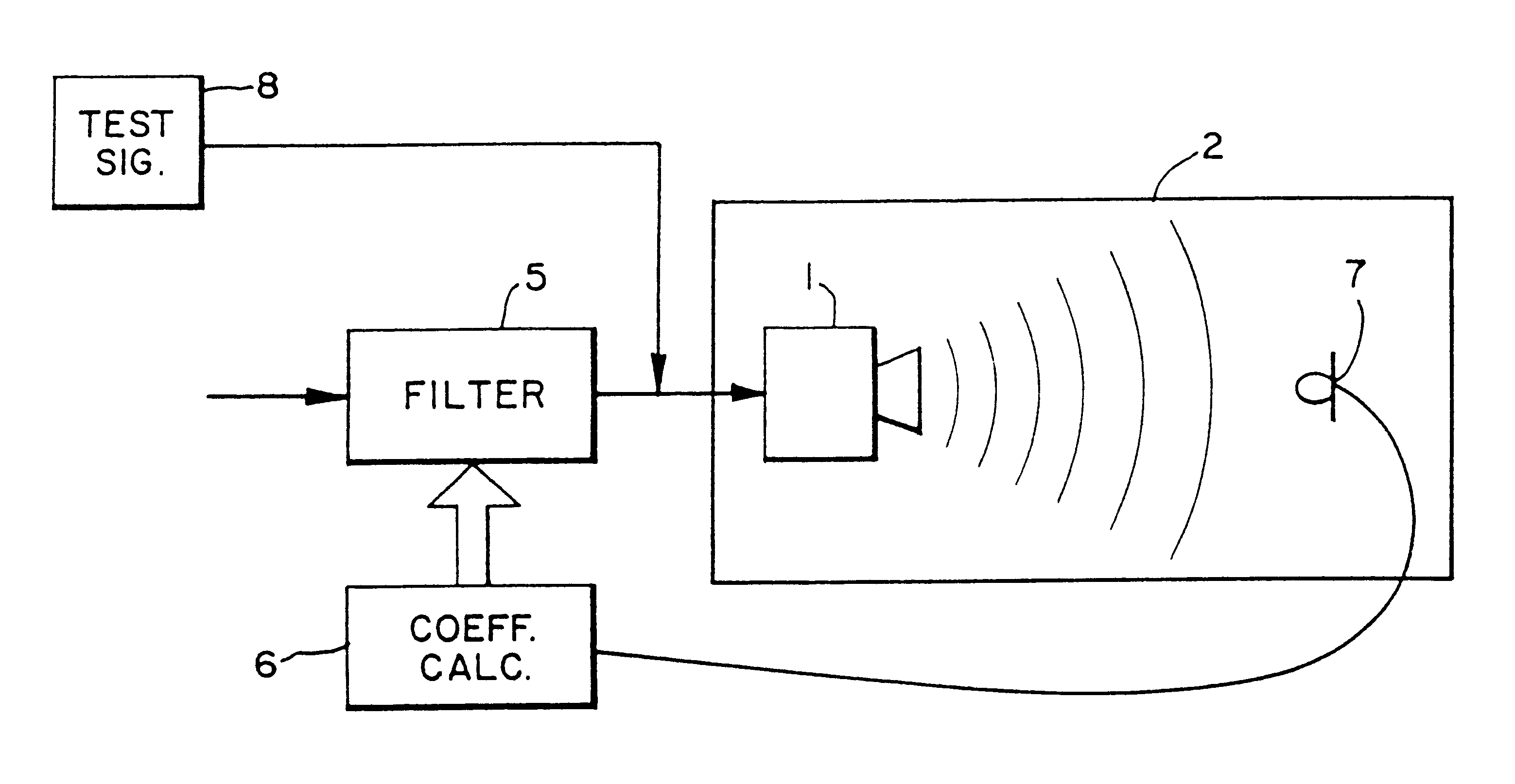
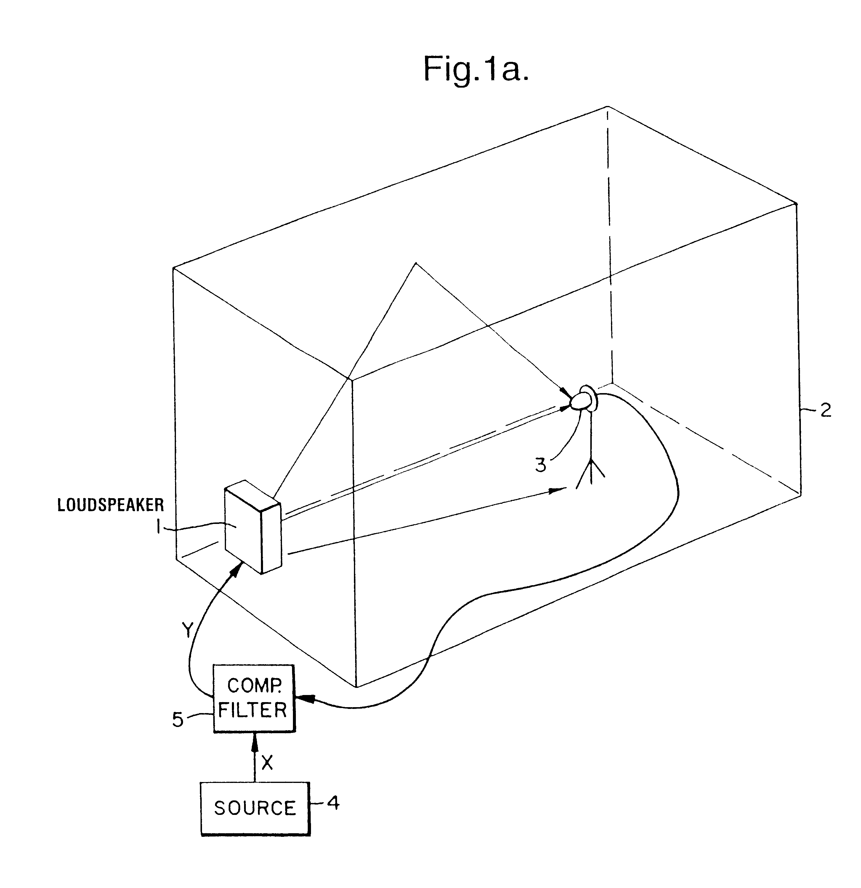
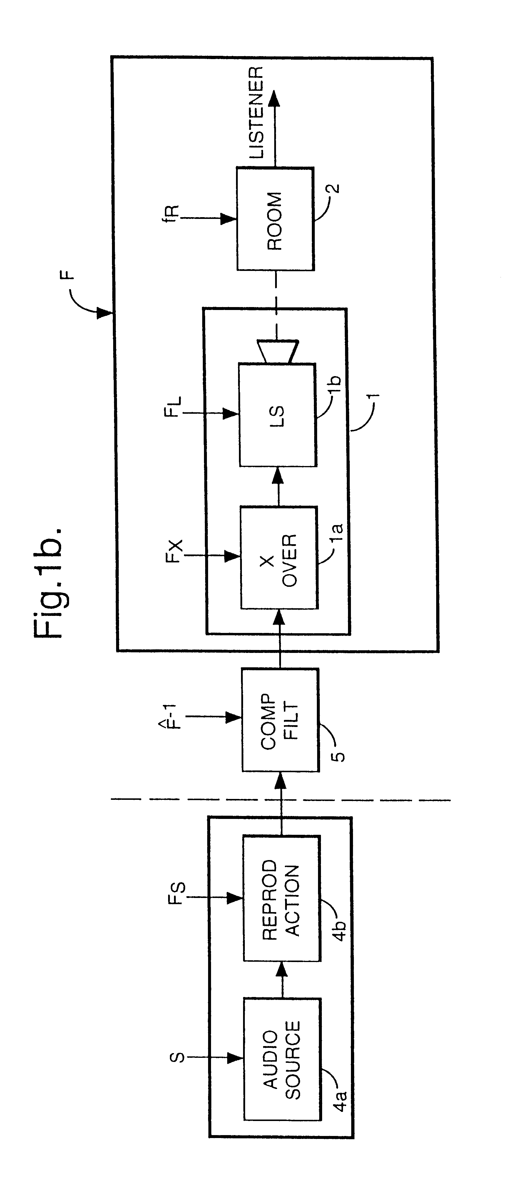
Referring to FIG. 1a, a loudspeaker 1 is positioned within a room or other acoustic environment 2. Also within the room 2 is a listening point 3; a microphone at this point is illustrated, but in use a human ear would take its place. The loudspeaker 1 is fed from a signal source 4 an electrical signal representing a sound signal to be reproduced by the loudspeaker 1. In the electrical path between the source 4 and loudspeaker 1 is the compensating filter apparatus 5 the subject of the present invention.

The acoustic signal generated by the loudspeaker in response to the electrical signal it receives traverses the acoustic environment 2 by several paths; through the floor, directly through the air, and via multiple reflections from the walls, floor and ceiling. The walls, floor and ceiling will to some extent attenuate the acoustic signal with each reflection. If the degree of attenuation is relatively low, long resonances lasting several seconds can build up depending u...


PUM


Abstract

A prefilter (5) for an audio system comprising a loudspeaker (1) in a room (2), which corrects both amplitude and phase errors due to the loudspeaker (1) by a linear phase correction filter response and corrects the amplitude response of the room (2) whilst introducing the minimum possible amount of extra phase distortion by employing a minimum phase correction filter stage. A test signal generator (8) generates a signal comprising a periodic frequency sweep with a greater phase repetition period than the frequency repetition period. A microphone (7) positioned at various points in the room (2) measures the audio signal processed by the room (2) and loudspeaker (1), and a coefficient calculator (6) (e.g. a digital signal processor device) derives the signal response of the room and thereby a requisite minimum phase correction to be cascaded with the linear phase correction already calculated for the loudspeaker (1). Filter (5) may comprise the same digital signal processor as the coefficient calculator (6). Applications in high fidelity audio reproduction, and in car stereo reproduction.

Description

1. Field of the InventionThis invention relates to filtering audio signals to compensate the effects of acoustic and / or electrical stages in the signal path from the original sound source to the human ear.2. Discussion of Prior ArtIn general, this signal path will include a pickup receiving the sound, and converting it to, typically, an electrical signal; signal transmission channels; signal processing (e.g. filtering, tone control or noise reduction); signal transmission, or alternatively recording on to a record carrier; signal reception or alternatively replaying from the record carrier; a further transmission link; and reconversion into an audio signal via an electro-acoustic transducer. If the transducer is a loudspeaker, the final stage in the path is transmission through an acoustic environment (typically a room) to the human ear.Associated with each stage of the signal path is a transfer characteristic, and at various stages in the path attempts may be made to filter the sig...

Claims


Application Information

Patent Timeline
Patent Type & Authority Patents(United States)
IPC IPC(8): H03H21/00H03G5/16H04R3/04H04S7/00H04R29/00
CPCH03G5/005H03G5/165H03H21/0012H04R3/04H04S7/305H04S7/307H04R29/001H04S7/301H04S7/40
Inventor CRAVEN, PETER GRAHAMGERZON, MICHAEL ANTHONY
Owner CRAVEN PETER GRAHAM
Why Eureka
Try Eureka