Magnetic resonance imaging device and timing misalignment detection method thereof

a magnetic resonance imaging and timing misalignment technology, applied in the field of magnetic resonance imaging technique, can solve the problems of output timing misalignment among the respective power sources, artifact and distortion in the photographed image, and achieve the effect of high accuracy

Active Publication Date: 2019-10-01
FUJIFILM HEALTHCARE CORP
View PDF16 Cites 0 Cited by
  • Summary
  • Abstract
  • Description
  • Claims
  • Application Information

AI Technical Summary

Benefits of technology

[0010]The present invention has been made in consideration of the aforementioned circumstances. It is an object of the present invention to provide a technique for accurately detecting the output timing misalignment between the respective power sources which are intended to perform parallel driving of the positive-side subcoils and the negative-side subcoils which are divided from the magnetic field gradient coil without employing the additional measurement device. It is an object of the present invention to provide an adjustment technique for correcting the output timing misalignment between the respective power sources so as to eliminate the phase distortion in the image caused by the misalignment without employing the additional measurement device.Solution to Problem

Problems solved by technology

Use of a plurality of power sources for driving may cause the problem of output timing misalignment among the respective power sources.
Variance in characteristics of the power sources and the difference in impedance among subcoils may be the main cause of the timing misalignment.
The timing misalignment further leads to the artifact and distortion in the photographed image.

Method used


Image

  • Magnetic resonance imaging device and timing misalignment detection method thereof
  • Magnetic resonance imaging device and timing misalignment detection method thereof
  • Magnetic resonance imaging device and timing misalignment detection method thereof

Examples


« first embodiment »

«First Embodiment»

[0029]A first embodiment according to the present invention will be described. In all the drawings for explaining the embodiments of the present invention, the element with the same function will be designated with the same code, and repetitive explanation thereof will be omitted.

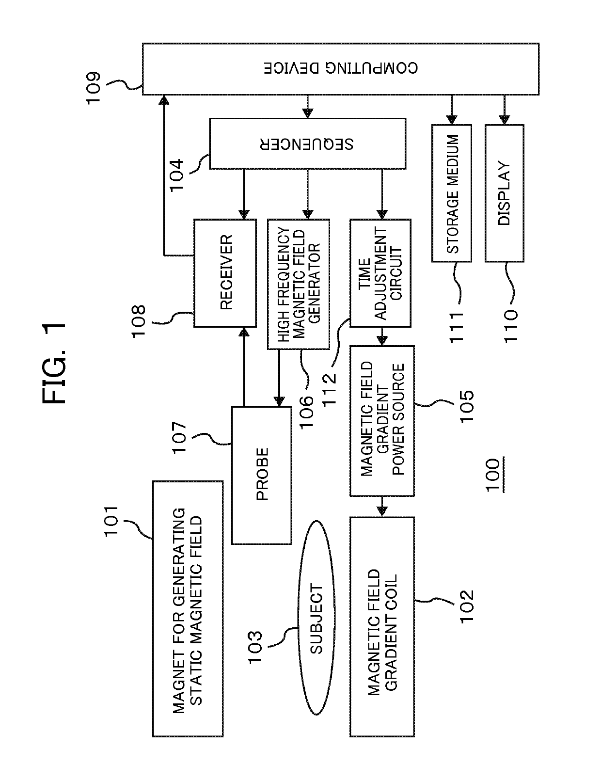
[0030]The MRI system according to the embodiment will be described. FIG. 1 is a block diagram schematically showing a structure of an MRI system 100 according to the embodiment. The MRI system 100 includes a magnet 101 for generating the static magnetic field, a magnetic field gradient coil 102 for generating the magnetic field gradient, a sequencer 104, a magnetic field gradient power source 105, a high frequency magnetic field generator 106, a probe 107 for irradiating the high frequency magnetic field and detecting a nuclear magnetic resonance signal, a receiver 108, a computing device 109, a display 110, and a storage medium 111. A subject (for example, living body) 103 is laid on a be...

« modified example of embodiment »

«Modified Example of Embodiment»

[0084]In the first embodiment, the echo is measured by executing four kinds of timing misalignment detection pulse sequences so as to sequentially cancel the phase distribution unique to probe mixed with each phase of the respective projection images, the phase distribution caused by ununiformity in the static magnetic field, and the phase rotation caused by misalignment of the reception signal during the A / D period. In the case where such factors as the phase distribution unique to probe and ununiformity in the static magnetic field are small, which are substantially uninfluential to detection of the drive timing misalignment of the magnetic field gradient subsoil, it is possible to use easier measurement process which omits the aforementioned cancelling process.

[0085]One of the aforementioned modified examples employs only the pulse sequences for measuring the echo Nos. 1 and 4 among four kinds of the pulse sequences for the echo Nos. 1 to 4 shown i...


PUM


Abstract

A magnetic resonance imaging device produces a magnetic field gradient with parallel driving of positive-side subcoils and negative-side subcoils with different power sources in the magnetic field gradient direction, to detect a misalignment in drive timing of the positive side and the negative side. Pulse sequences for timing misalignment detection having a slice magnetic field gradient pulse and a read-out magnetic field gradient pulse in the same direction as a magnetic field gradient of interest are executed. A positive-side slice echo and a negative-side slice echo of the magnetic field gradient are acquired. A phase difference between a positive-side projection image and a negative-side projection image is derived by computation with phase error from other factors being removed. From the slope of the phase difference with respect to a location, the drive timing misalignment between the positive-side subcoil and the negative-side subcoil of the magnetic field gradient production is detected.

Description

TECHNICAL FIELD[0001]The present invention relates to a magnetic resonance imaging technique, and more particularly, to an approach for detecting timing misalignment between the power sources for driving the magnetic field gradient coils so as to adjust the detected misalignment.BACKGROUND ART[0002]The magnetic resonance imaging (MRI) system is a medical image diagnostic device configured to apply a high frequency magnetic field and a magnetic field gradient to a subject laid in a static magnetic field, measure the signal generated from the subject through nuclear magnetic resonance, and form an image of the signal.[0003]The magnetic field gradient intended to generate the one-dimensional magnetic field intensity distribution in a space around the subject is used for imparting the location information to the signal. Generally, the magnetic field gradient generator includes a coil and a power source for driving the coil. As it is necessary to impart three-dimensional location informa...

Claims


Application Information

Patent Timeline
Patent Type & Authority Patents(United States)
IPC IPC(8): G01R33/385G01R33/58G01R33/54G01R33/565
CPCG01R33/3852G01R33/56572G01R33/58G01R33/546
Inventor TANIGUCHI, YOTAKIZAWA, MASAHIROYATSUO, TAKESHIKURATANI, ATSUSHI
Owner FUJIFILM HEALTHCARE CORP
Why Eureka
Try Eureka