
Radar transmitter unintentional modulation klystron output phase modeling method

A technology of output phase and unintentional modulation, applied in computer-aided design, instruments, calculations, etc., can solve problems such as phase distortion of klystron amplifiers, achieve the effect of eliminating voltage fluctuations and improving sensitivity

Active Publication Date: 2021-06-25
CHENGDU JINJIANG ELECTRONICS SYST ENG
View PDF5 Cites 0 Cited by
  • Summary
  • Abstract
  • Description
  • Claims
  • Application Information

AI Technical Summary

Problems solved by technology

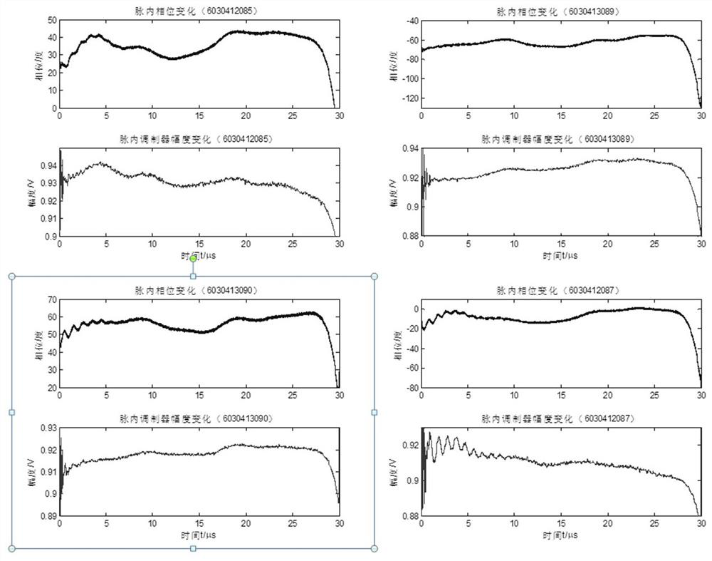
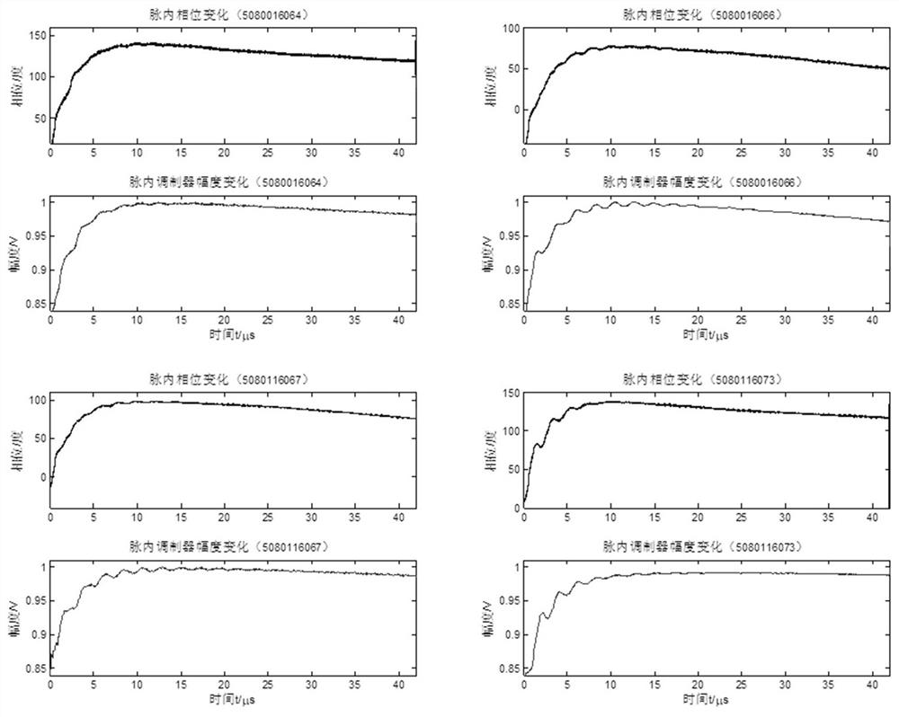
[0005] The purpose of the present invention is to overcome the deficiencies in the prior art, to provide a radar transmitter unintentional modulation klystron output phase modeling method, for eliminating the klystron amplifier phase distortion problem caused by the voltage fluctuation of the pulse modulator

Method used


Image

  • Radar transmitter unintentional modulation klystron output phase modeling method
  • Radar transmitter unintentional modulation klystron output phase modeling method
  • Radar transmitter unintentional modulation klystron output phase modeling method

Examples


Embodiment Construction

[0064] The technical solution of the present invention is further described in detail below in conjunction with specific examples, but the protection scope of the present invention is not limited to the following description.

[0065] A typical dual-chamber klystron consists of an electron gun (including filament, cathode, anode, etc.), an input chamber, an electron drift tube, an output chamber, and a collector. The essence of the klystron amplifier to amplify the microwave signal is to convert the energy of the DC power supply (modulator output) into microwave energy through the electron injection as the medium. The DC voltage output by the pulse modulator (usually up to tens of kilovolts) U L Acting between the cathode and anode of the electron gun, the electrons generated by the electron gun are accelerated to generate an electron beam with a certain speed and density, and the electron beam enters the drift tube through the gap in the input cavity. The RF excitation signa...


PUM


Abstract

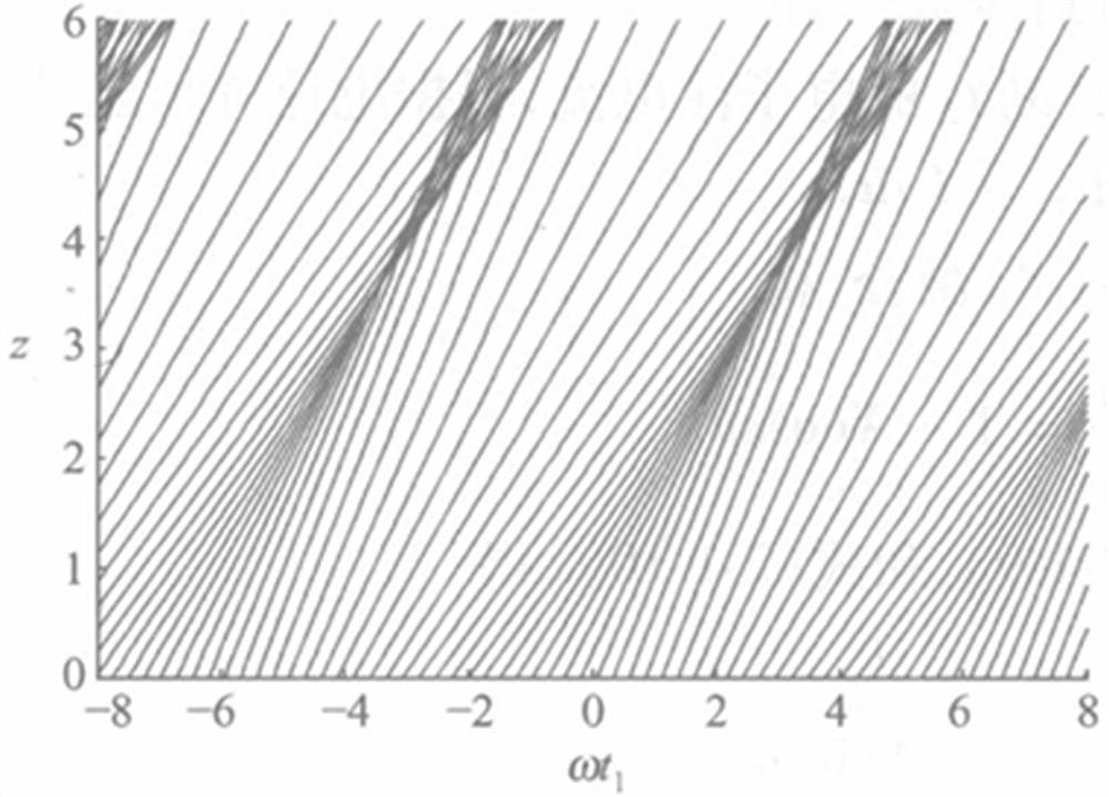
The invention relates to a radar transmitter unintentional modulation klystron output phase modeling method, and the method comprises the steps of carrying out the distortion analysis of the output phase of a klystron, obtaining the fluctuation quantity of the output phase lag of the klystron, which can be represented in description. By means of the klystron output phase model, the problem of klystron amplifier phase distortion caused by voltage fluctuation of the pulse modulator is solved, and the klystron output phase sensitivity is improved.

Description

technical field [0001] The invention relates to the field of radar transmitters, in particular to a method for modeling the output phase of a radar transmitter's unintentional modulation klystron. Background technique [0002] With the development of electronic information technology, electronic reconnaissance has become an important means of obtaining enemy intelligence. Search and detect the enemy's radiation source signal from the complex electromagnetic environment, process and extract the signal features to complete the identification and location of the radiation source, and further infer the type of the radiation source, which has an important military role in electronic warfare. significance. The traditional radiation source identification uses the basic characteristics of the signal, such as carrier frequency, pulse width, pulse repetition period, modulation mode of intra-pulse and inter-pulse signals, etc., to classify and identify. Its advantages are simple struc...

Claims


Application Information

Patent Timeline
Patent Type & Authority Applications(China)
IPC IPC(8): G06F30/367
CPCG06F30/367
Inventor 吕晖付家林徐晓天蔡东孙聚芳
Owner CHENGDU JINJIANG ELECTRONICS SYST ENG
Learn More