Detector capable of rotating and moving

A technology of detectors and rotating parts, which is applied in the field of detection equipment, and can solve problems such as the inability to effectively control the speed of the rotation and movement of the detector, and the inability of the detector to accurately detect the external environment.

Pending Publication Date: 2021-12-10
TENGZHOU FEITIAN LASER AUTOMATION TECH
View PDF0 Cites 0 Cited by
  • Summary
  • Abstract
  • Description
  • Claims
  • Application Information

AI Technical Summary

Problems solved by technology

[0005] The purpose of the embodiments of the present invention is to provide a rotating detector, which aims to solve the problem that when the existing detector is rotating and moving, the staff cannot effectively control the speed of the detector rotating and moving, resulting in the detector being unable to communicate with the outside. The problem of accurate exploration of the environment

Method used


Image

  • Detector capable of rotating and moving
  • Detector capable of rotating and moving
  • Detector capable of rotating and moving

Examples


Embodiment Construction

[0029] In order to make the object, technical solution and advantages of the present invention clearer, the present invention will be further described in detail below in conjunction with the accompanying drawings and embodiments. It should be understood that the specific embodiments described here are only used to explain the present invention, not to limit the present invention.

[0030] The specific implementation of the present invention will be described in detail below in conjunction with specific embodiments.

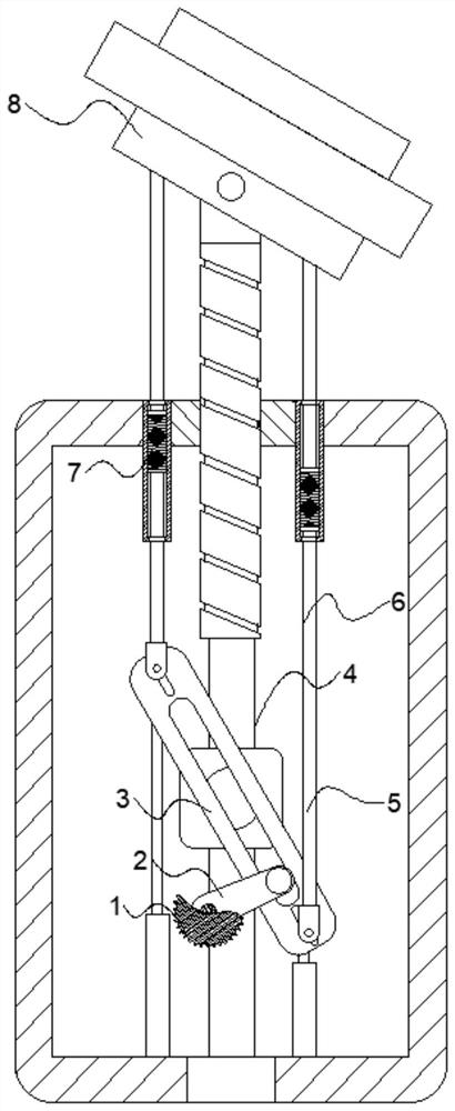
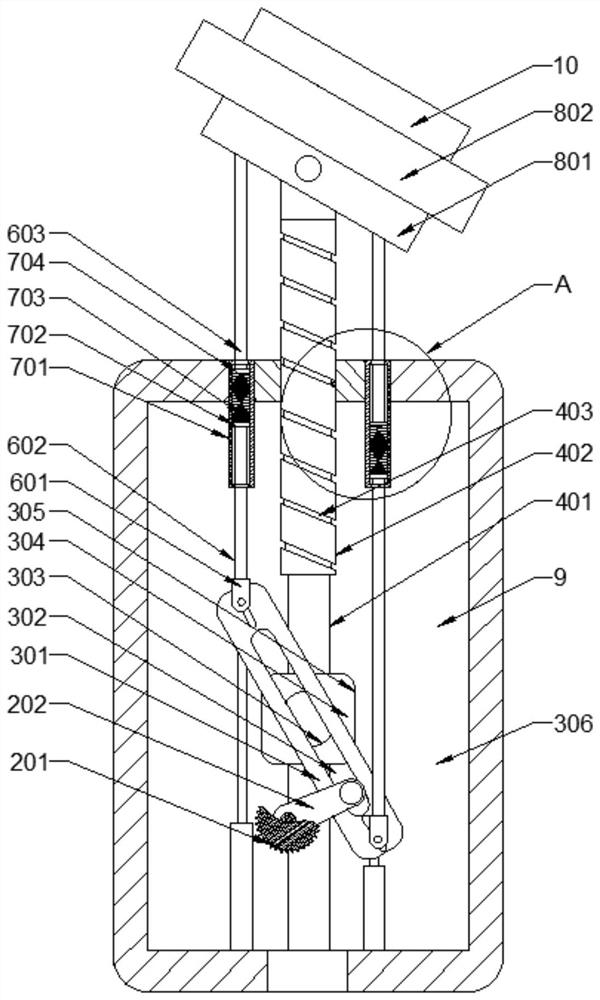
[0031] see Figure 1~2 , provided for an embodiment of the present invention, a rotating detector includes a mounting mechanism 8, a device body 9 and a detector 10, the device body 9 is connected to the mounting mechanism 8, and further includes:

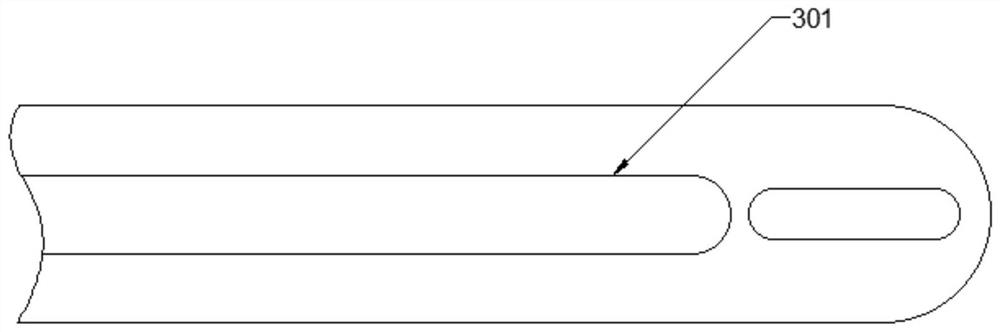
[0032] The rotation movement mechanism 1 is movably connected with the device body 9 and used to drive the detector 10 to move and rotate. The rotation movement mechanism 1 includes a transmission member B301, a driv...


PUM


Abstract

The invention is applicable to the technical field of detection equipment, and provides a detector capable of rotating and moving, which comprises a mounting mechanism, a device body and a detector body, wherein the device body is connected with the mounting mechanism, and the detector also includes a rotary moving mechanism which is movably connected with the device body and is used for driving the detector to move and rotate, wherein the rotary moving mechanism comprises a transmission part B, a driving assembly, a rotary moving assembly and a speed adjusting assembly; the rotary moving assembly comprises a sliding part A, a rotating part, a sliding groove A and a sliding part B. The sliding groove A is in sliding fit with the sliding part B. The rotating part is connected with the mounting mechanism. According to the invention, the rotational movement rate of the detector can be controlled.

Description

technical field [0001] The invention belongs to the technical field of detection equipment, in particular to a rotating and moving detector. Background technique [0002] With the development of society, great changes have taken place in people's working and living styles. It can be said that earth-shaking changes have taken place in the detection field from the early manual field survey to the current use of various powerful detectors for detection. [0003] The existing detector basically has the function of rotating and moving, which makes the detector more flexible and can effectively detect the surrounding environment. [0004] However, when the existing detectors are rotating and moving, the staff cannot effectively control the speed of the detectors rotating and moving, resulting in the detectors being unable to accurately detect the external environment. Contents of the invention [0005] The purpose of the embodiments of the present invention is to provide a dete...

Claims


Application Information

Patent Timeline
Patent Type & Authority Applications(China)
IPC IPC(8): G01D11/00
CPCG01D11/00
Inventor 满中桦
Owner TENGZHOU FEITIAN LASER AUTOMATION TECH
Why Eureka
Try Eureka