Laser scanning device and laser scanning method

A laser scanning device, laser scanning technology, applied in the field of laser applications

Pending Publication Date: 2021-12-28
陈怀超
View PDF0 Cites 0 Cited by
  • Summary
  • Abstract
  • Description
  • Claims
  • Application Information

AI Technical Summary

Problems solved by technology

[0004] The purpose of the present invention is to provide a laser scanning device and a laser scanning method to solve the problem of uniform motion of the point of action of the pan / tilt load in a certain plane

Method used


Image

  • Laser scanning device and laser scanning method
  • Laser scanning device and laser scanning method
  • Laser scanning device and laser scanning method

Examples


Embodiment Construction

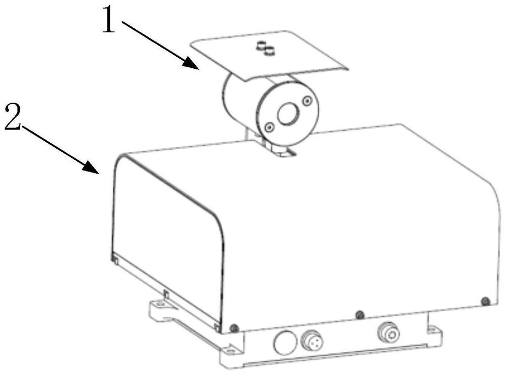
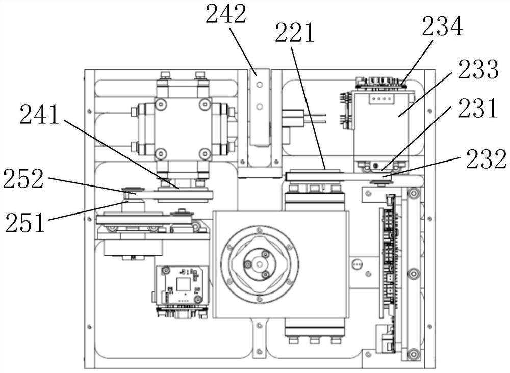
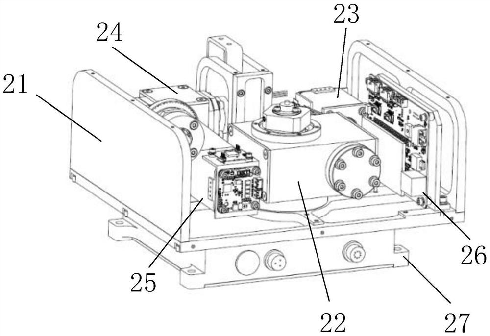
[0070] The present invention will be further described in detail below in conjunction with the accompanying drawings and embodiments. It should be understood that the specific embodiments described here are only used to explain the present invention, but not to limit the present invention. In addition, it should be noted that, for the convenience of description, only some structures related to the present invention are shown in the drawings but not all structures.

[0071] In the description of the present invention, unless otherwise clearly specified and limited, the terms "connected", "connected" and "fixed" should be understood in a broad sense, for example, it can be a fixed connection, a detachable connection, or an integrated ; It can be a mechanical connection or an electrical connection; it can be a direct connection or an indirect connection through an intermediary, and it can be the internal communication of two components or the interaction relationship between two ...


PUM


Abstract

The invention belongs to the technical field of laser application, and discloses a laser scanning device and a laser scanning method. The laser scanning device comprises a laser scanning assembly and a holder assembly, and the laser scanning assembly is detachably connected to the holder assembly; the holder assembly comprises a U-shaped support, a first worm and gear speed reducer, a first execution module, a second worm and gear speed reducer, a second execution module and a main control board, and the first worm and gear speed reducer, the first execution module, the second worm and gear speed reducer, the second execution module and the main control board are fixed to the U-shaped support, the first worm and gear speed reducer and the first execution module can implement second-stage orientation transmission, the second worm and gear speed reducer and the second execution module can perform three-stage pitching transmission, so that a laser action point moves at a constant speed on the ground and a certain plane, and the laser action point is a laser group array and can achieve a laser beam scanning effect.

Description

technical field [0001] The invention relates to the technical field of laser applications, in particular to a laser scanning device and a laser scanning method. Background technique [0002] Laser scanning, because of its long-distance and precise detection performance, is widely used in the field of non-contact distance measurement. When the action object of laser scanning is in motion, the movement speed of the action point will have a great impact on laser scanning. When the vertical height between the load and the point of action is small, the small moving distance of the point of action will cause the pitching speed of the load to change greatly. [0003] In a two-dimensional pan / tilt or turntable, when the point of action is a uniform motion on the ground or a horizontal plane, the transmission control is more difficult for a two-dimensional pan / tilt with a lower height, so a high-precision pan / tilt is required to load A laser scanner is used to scan objects in motio...

Claims


Application Information

Patent Timeline
IPC IPC(8): G01S7/481
CPCG01S7/4817
Inventor 陈怀超
Owner 陈怀超
Why Eureka
Try Eureka