Warp drawing equipment for canvas production

A kind of equipment and canvas technology, applied in the field of warp pulling equipment, can solve problems such as affecting the quality of textile products, yarn wear, and affecting the respiratory health of staff.

Pending Publication Date: 2022-01-07
怀化顺天帆布有限责任公司
View PDF5 Cites 0 Cited by
  • Summary
  • Abstract
  • Description
  • Claims
  • Application Information

AI Technical Summary

Problems solved by technology

[0004] The warp drawing device is responsible for conveying the wound yarn into the warp knitting machine with a stable tension, so there will be long-term friction between the yarn and the warp drawing device, which will cause the part of the yarn to be worn and cause the air to be full of fine particles. fiber, which affects the respiratory health of the staff, and also affects the quality of the finished textile;

Method used


Image

  • Warp drawing equipment for canvas production
  • Warp drawing equipment for canvas production
  • Warp drawing equipment for canvas production

Examples


Embodiment 1

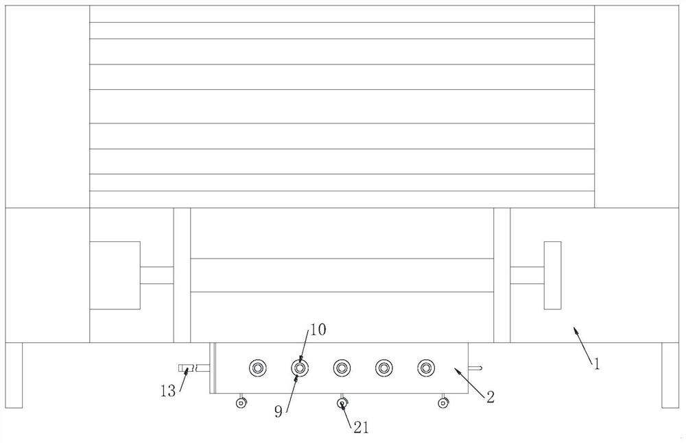
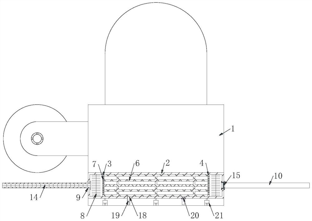
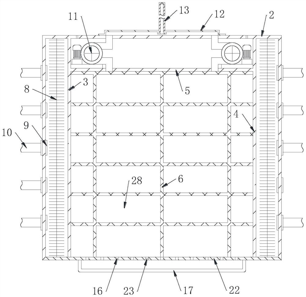
[0026] see Figure 1-4 As shown, a warp-drawing device for canvas production includes a warp-drawing machine 1, a dust removal box 2, a left partition 3, a right partition 4 and a dust removal unit; the lower end of the warp-drawing machine 1 is plugged with Dust removal box 2; one side of the dust removal box 2 is grooved and detachably fixed with a quick release plate 22; the interior of the dust removal box 2 is symmetrically sealed and fixed with a left partition plate 3 and a right partition plate 4 ; Between the left partition plate 3 and the right partition plate 4, the middle partition plate 5 is sealed and fixed; the inside of the dust removal box 2 is provided with a dust removal unit; the dust removal unit includes a filter screen 7, a first Metal mesh 8, threaded interface 9 and first gooseneck 10; All grooves in the left partition plate 3 and the right partition plate 4 are fixed with filter screens 7; The left partition plate 3 and the right partition A first me...

Embodiment 2

[0035] see Figure 5 As shown in Comparative Example 1, as another embodiment of the present invention, the first gooseneck 10 is sleeved with a sleeve 24; the sleeve 24 is fixed with a fixing plate 25; the fixing An elastic member 26 is fixedly connected to the plate 25; the other end of the elastic member 26 is fixedly connected with a clamping plate 27; the clamping plate 27 is slidably sleeved on the sleeve 24; Make the spacing between the clamping plate 27 and the fixed plate 25 increase, so that it can be clamped on other objects, and the clamping plate 27 and the fixed plate 25 are kept clamped by the elastic member 26, so that the first gooseneck 10 Can be fixed to or fixed to other objects.

[0036] The working principle is that the negative pressure machine 11 is connected to the mains to work, and then the air negative pressure is generated, and the fiber filter block 6, the filter screen 7, the threaded interface 9 and the first gooseneck 10 are in contact with th...


PUM


Abstract

The invention belongs to the field of canvas, and particularly relates to warp drawing equipment for canvas production. The warp drawing equipment for canvas production comprises a warp drawing machine, a dust removal box body, a left partition plate, a right partition plate and a dust removal unit, wherein a dust removal box body is inserted into the lower end of the warp drawing machine; a groove is formed in one side of the dust removal box body and is detachably and fixedly connected with a quick release plate; the left partition plate and the right partition plate are symmetrically, hermetically and fixedly connected into the dust removal box body; a middle partition plate is fixedly connected between the left partition plate and the right partition plate in a sealed mode; and a dust removal unit is arranged in the dust removal box body. A negative pressure machine is externally connected with a mains supply to work, then air negative pressure is generated and makes contact with outside air through a fiber filter block, a filter screen, a threaded connector and a first gooseneck pipe, then the position of the first gooseneck pipe is changed to be located below winding yarns, and fine fibers abraded from the yarns are sucked into the first gooseneck pipe along with the air and then are filtered by the filter screen and the fiber filter block, so that the air is purified, and the breathing of workers is kept healthy.

Description

technical field [0001] The invention relates to the field of canvas, in particular to warp drawing equipment for canvas production. Background technique [0002] The warp drawing equipment is one of the auxiliary equipment of the warp knitting machine. It is responsible for pulling the yarn and supplying it to the warp knitting machine for weaving. It is a common equipment in the textile industry and a necessary equipment for automatic and efficient weaving. [0003] Canvas is a thicker cotton or linen fabric, which is made by warp and weft weaving technology. The cloth made in this way was first used on ships, so it is called canvas. [0004] The warp drawing device is responsible for conveying the wound yarn into the warp knitting machine with a stable tension, so there will be long-term friction between the yarn and the warp drawing device, which will cause the part of the yarn to be worn and cause the air to be full of fine particles. fiber, which affects the respirator...

Claims


Application Information

Patent Timeline
IPC IPC(8): D04B35/32
CPCD04B35/32
Inventor 范建平陈汉雄黄雄中
Owner 怀化顺天帆布有限责任公司
Why Eureka
Try Eureka