Humidifying device with water level monitoring function and water level monitoring method and equipment

A water level monitoring and humidification technology, applied in the field of medical devices, can solve the problems of water level monitoring misjudgments, false alarms, etc., and achieve the effect of simplifying the workload

Pending Publication Date: 2022-01-14
HUNAN MICOME ZHONGJIN MEDICAL SCI & TECH DEV CO LTD
View PDF1 Cites 0 Cited by
  • Summary
  • Abstract
  • Description
  • Claims
  • Application Information

AI Technical Summary

Problems solved by technology

Comparison documents China uses infrared light intensity to judge the water level in the humidifier, which is likely to cause misjudgment of water level monitoring and generate false alarms

Method used


Image

  • Humidifying device with water level monitoring function and water level monitoring method and equipment

Examples


Embodiment 1

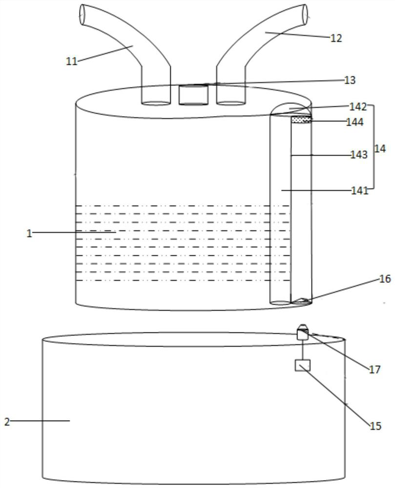
[0035] A humidification device with water level monitoring function, such as figure 1As shown, it includes a humidification device water box 1, wherein the upper part of the humidification device water box 1 is provided with an air inlet 11, an air outlet 12 and a water inlet 13, and the inside of the humidification device water box 1 is provided with a U-shaped communication pipe 14, U The U-shaped communication pipe 14 is placed upside down inside the water box 1 of the humidification device. The U-shaped communication pipe 14 includes a first pipe 141, a connecting portion 142 and a second pipe 143. The port of the first pipe 141 communicates with the inside of the water box 1 of the humidification device. The port of the second pipeline 143 is a pressure collection port, and the pressure collection port is in a sealed state when no pressure collection is performed.

[0036] In the specific implementation process, the upper part of the water box 1 of the humidification devi...

Embodiment 2

[0047] A water level monitoring method of a humidification device with a water level monitoring function, the idea and method are as follows:

[0048] S1. According to the diameters of the first pipeline and the second pipeline and the size of the designed airway, the relationship between the water level height H and the pressure P is calculated through experimental simulation.

[0049] The U-shaped connecting pipe U1 is composed of the water box of the humidification device and the first pipe, and the U-shaped connecting pipe U2 is composed of the first pipe and the second pipe. According to the principle of U-shaped pipe: when both ends of the U-shaped pipe are in contact with the atmosphere, The pressure at both ends is atmospheric pressure, and the liquid level at both ends should be the same; similarly, when the first pipe is sealed, as the water level in the water box of the humidification device rises, the pressure in the first pipe increases. The U-shaped connecting pi...

Embodiment 3

[0056] A respiratory support device, comprising the above-mentioned humidification device with water level monitoring function.


PUM


Abstract

The invention discloses a humidifying device with a water level monitoring function and a water level monitoring method and equipment. A U-shaped communicating pipeline is arranged in a water box of the humidifying device, the U-shaped communicating pipeline is inversely arranged in the water box of the humidifying device and comprises a first pipeline, a connecting part and a second pipeline, a port of the first pipeline is communicated with the interior of the water box of the humidifying device, a port of the second pipeline is a pressure collecting port, and the pressure collecting port is in a sealed state when not used for pressure collection. According to the invention, the water box of the humidifying device and the first pipeline form an U-shaped connecting pipe U1, the first pipeline and the second pipeline form an U-shaped connecting pipe U2, the water level height in the water box is calculated according to the water level height relation, accurate water level alarm can be achieved by monitoring the water level in the water box of the humidifying device, and dry burning and overflow due to the too high water level are prevented; and the use time after water adding can be accurately calculated, so that the user can add water according to the use time, and the work of accompanying personnel is relieved.

Description

technical field [0001] The invention belongs to the technical field of medical devices, and in particular relates to a humidification device with a water level monitoring function, a water level monitoring method and equipment. Background technique [0002] Existing humidification devices do not have accurate water level monitoring functions, but only have anti-dry function and high and low water level monitoring functions. Among them, the anti-dry function is to detect the temperature of the heating plate through the temperature sensor at the bottom of the heating plate to achieve the anti-dry function. According to the principle of heat transfer, when there is water, the temperature of the heating plate is transferred to the humidified water in the water box, and the water temperature will not exceed 100 ℃, so the maximum temperature of the heating plate of the humidification device is about 100 ℃. When the water in the humidification water box is used up, the continuous h...

Claims


Application Information

Patent Timeline
Patent Type & Authority Applications(China)
IPC IPC(8): A61M16/16A61M16/00
CPCA61M16/162A61M16/0051A61M2205/3382A61M2205/3331
Inventor 戴征王磊
Owner HUNAN MICOME ZHONGJIN MEDICAL SCI & TECH DEV CO LTD
Why Eureka
Try Eureka