
Eureka
For R&D, Eureka makes reading and utilizing patents & technical documents easy.
Eureka AIR
Designed for self-driven R&D workflows. Generate viable solutions, solve complex R&D challenges, empower your innovation with AI.

Eureka Materials
Designed for material experts only. Revolutionize your material R&D, from search, analyze, to developing new materials.

TechResearch
Generate reliable direction feasibility study reports for your R&D in just a few steps.

TechSeek
Discover and master advanced knowledge NOW. Basics, ideas, possibilities, all at once.

TechMind
As an expert in R&D Theories, TechMind can generates customized viable solutions instantly.

TechRisk
Analyze your overall solution with one click, know your potential R&D risks in advance.

TechMonitor
Get weekly tech updates, stay abreast of the latest tech innovations and key insights.
Blowing and suction switching structure for blowing and suction fan and blowing and suction fan
A technology of blowing and sucking fans and switching structures, which is applied to components of pumping devices for elastic fluids, machines/engines, mechanical equipment, etc., and can solve problems such as weak suction or suction performance, high cost, and complex structure
- Summary
- Abstract
- Description
- Claims
- Application Information
AI Technical Summary
Problems solved by technology
Method used
Image

Examples
Embodiment 1
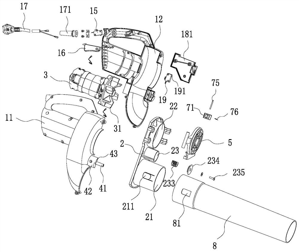
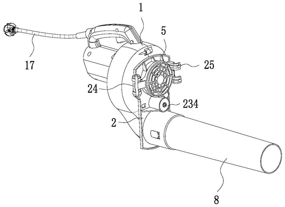
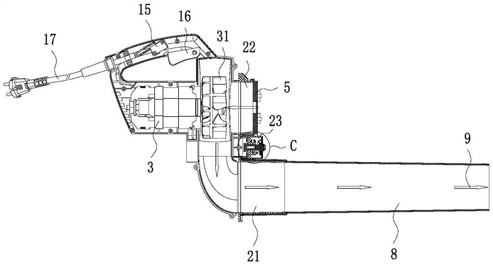
[0045] like Figure 1 to Figure 19 As shown, this embodiment shows a blowing-suction conversion structure for a blower-suction fan, including a casing 1 and a bracket 2, the surface of the casing 1 is provided with an air inlet 13 and an air outlet 14, and the air inlet 13 Between the air outlet 14 and the stud 41 for mounting the bracket 2, the bracket 2 is provided with a first air outlet 21 and a second air outlet 22, the bracket 2 is rotatably connected with the stud 41, and the first air outlet An air duct 8 is installed on the 21, and an air inlet cover 5 or a dust collection bag 6 is installed on the second air outlet 22. When the first air outlet 21 is connected with the air inlet 13, the blower is in a suction mode, When the first air outlet 21 is docked with the air outlet 14, the blowing and suction fan is in the blowing mode, and the bracket 2 rotates around the stud 41 to switch between the blowing and suction modes.
[0046] In this embodiment, the air inlet 13 ...
Embodiment 2
[0056] like Figures 1 to 9 As shown, this embodiment shows a blower, the blower is provided with the conversion structure of the blower as described in Embodiment 1 or other same embodiments, the casing 1 in this embodiment includes a left The casing 111 and the right casing 121, the left casing 111 and the right casing 121 are spliced by screws 235, the power cord 17 is installed on the right casing 121, and the connection between the power cord 17 and the right casing 121 A power supply sheath 171 is sheathed at the center, and the casing 1 includes a handle on which a power switch 15 and a power supply pressing plate 16 are arranged. The power cord 17 is connected to the power switch 15. By pressing the power supply Pressing plate 16 just can make power switch 15 open.
[0057] The switching process of the blowing mode of the blowing fan described in this embodiment is as follows:
[0058] Suction mode: the first air port 21 is docked with the air inlet 13, the second ...
PUM
 Abstract
Description
Claims
Application Information
 - R&D Engineer
- R&D Manager
- IP Professional
- Industry Leading Data Capabilities
- Powerful AI technology
- Patent DNA Extraction
Browse by: Latest US Patents, China's latest patents, Technical Efficacy Thesaurus, Application Domain, Technology Topic, Popular Technical Reports.
© 2024 PatSnap. All rights reserved.Legal|Privacy policy|Modern Slavery Act Transparency Statement|Sitemap|About US| Contact US: help@patsnap.com