Blowing and sucking conversion device and blowing and sucking fan

A conversion device and conversion frame technology, which is applied in construction, cleaning methods, road cleaning, etc., can solve problems such as difficulty in use, inconvenient switching operation, and difficult switching by operators, and achieve easy operation, simple structure, and convenient and quick use Effect

Active Publication Date: 2021-10-22
ZHEJIANG YAT ELECTRICAL APPLIANCE CO LTD
View PDF7 Cites 0 Cited by
  • Summary
  • Abstract
  • Description
  • Claims
  • Application Information

AI Technical Summary

Problems solved by technology

[0005]Both of the above are connected and switched between the single-channel air duct and the host to realize the switching of the blowing mode, and the single-channel air duct switching structure, When in use, the switching operation is not very convenient, it is difficult for the operator to switch, and it is difficult to use

Method used


Image

  • Blowing and sucking conversion device and blowing and sucking fan
  • Blowing and sucking conversion device and blowing and sucking fan
  • Blowing and sucking conversion device and blowing and sucking fan

Examples


Embodiment Construction

[0031] Below, the embodiments of the present invention are described in detail. In order to make the purpose, technical solutions and advantages of the embodiments of the present invention clearer, the technical solutions in the embodiments of the present invention will be clearly and completely described below in conjunction with the embodiments of the present invention. Obviously , the described embodiments are some, not all, embodiments of the present invention.

[0032] Therefore, the detailed description of the embodiments of the present invention provided below is not intended to limit the scope of the claimed invention, but merely represents selected embodiments of the present invention, based on the embodiments of the present invention, those of ordinary skill in the art All other embodiments obtained under the premise of no creative work belong to the protection scope of the present invention.

[0033] The terms used herein are intended to explain the embodiments, and...


PUM


Abstract

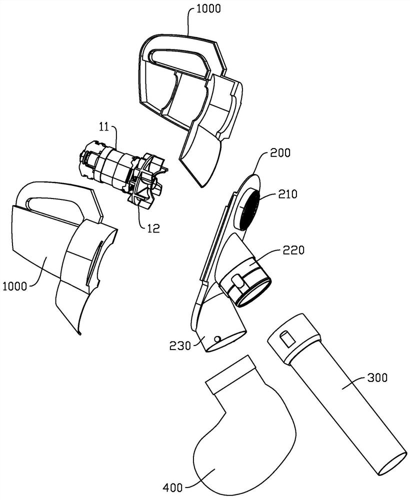
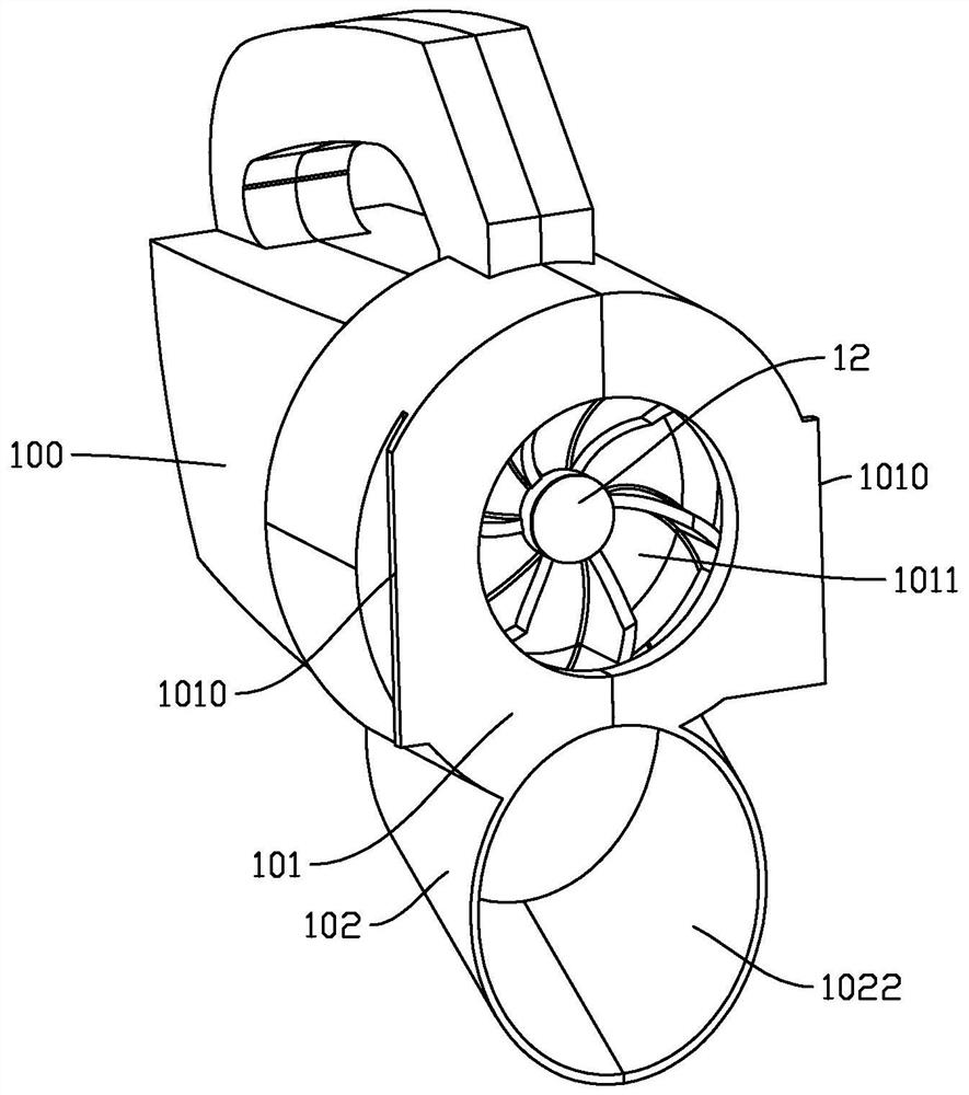
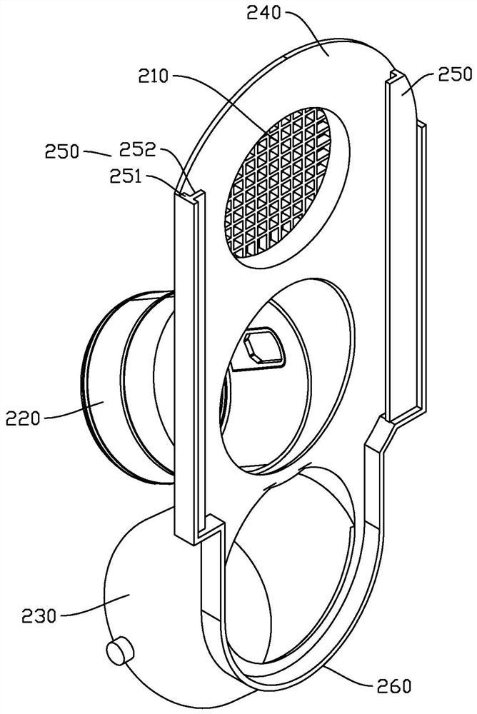
The invention discloses a blowing and suction conversion device and a corresponding blowing and suction fan, the blowing and suction conversion device comprises a main shell, a motor and a fan which are arranged in the main shell, the blowing and suction conversion device further comprises a conversion frame, and the conversion frame comprises a first channel, a second channel and a third channel; the main shell comprises an air inlet channel and an air outlet channel, the conversion frame is connected with the main shell, the conversion frame and the main shell can move in the radial direction under the condition that connection is not cut off, and therefore the air blowing mode and the air suction mode can be switched, in the air blowing mode, the air inlet channel is communicated with the first channel, and in the air suction mode, the air outlet channel is communicated with the second channel. The air outlet channel is communicated with the second channel; and in an air suction mode, the air inlet channel is communicated with the second channel, and the air outlet channel is communicated with the third channel. Blowing and sucking function conversion is achieved in a translation mode, and the blowing and suction conversion device has advantages of simple structure, easy operation and no use difficulty.

Description

technical field [0001] The invention relates to the technical field of cleaning tools, in particular to a blow-suction conversion device and a blow-suction blower. Background technique [0002] When cleaning dust, waste, leaves and other garbage, the fan structure with blowing and suction function is generally used for cleaning. The motor, the fan driven by the motor and the handle connected to the main casing, etc. The blowing and absorbing parts generally include the blowing pipe and the suction pipe connected to the air duct. The blowing and suctioning machine needs to have both blowing and suction functions. At present, in the axial flow In the structure of the fan blowing and sucking in the same pipe, one solution is to realize the forward and reverse rotation of the motor. The defect of this solution is that the performance of suction or suction is weak; the other solution is to realize the conversion of blowing and suction by rotating the motor assembly to switch the ...

Claims


Application Information

Patent Timeline
Patent Type & Authority Applications(China)
IPC IPC(8): E01H1/08
CPCE01H1/08
Inventor 金银刚陈洁
Owner ZHEJIANG YAT ELECTRICAL APPLIANCE CO LTD
Why Eureka
Try Eureka