Capacitor protection device

A capacitor protection and capacitor technology, applied to capacitors, fixed capacitor terminals, fixed capacitor components, etc., can solve problems such as inconvenience, increased heat dissipation, and inability to protect capacitors, and achieves simple and convenient operation, not easy to corrode and weather, prolong The effect of the service life

Inactive Publication Date: 2022-03-01
杭州绿中游智能科技有限公司
View PDF1 Cites 0 Cited by
  • Summary
  • Abstract
  • Description
  • Claims
  • Application Information

AI Technical Summary

Problems solved by technology

Shunt capacitors are generally installed outdoors. Due to long-term exposure to the external environment, some extreme weather such as heavy rain or high temperature may cause certain damage to the shunt capacitors. The existing method is simply Some protective measures are set inside the shunt capacitor, and it needs to be repaired or replaced at regular intervals, which cannot effectively achieve long-term protection, which is very inconvenient; the existing publication number CN201922066899.8 is a substation shunt capacitor protection device; through Set up a protective shell to protect it well. In case of heavy rain, the protective shell is closely attached to the capacitor body, so that the rainwater will not directly contact the capacitor body, avoiding long-term moisture and corrosion of the surface metal. In high temperature weather, The cooling fan and cooling window are set together to dissipate heat from the capacitor to ensure that the internal temperature can be maintained within a normal range. At the same time, two adjustable movable splints are set to clamp and fix the capacitor so that it can maintain a stable state for a long time. Adapting to capacitors of different lengths increases the practicability and adaptability of the device; parallel capacitors generally have their own casings, and installing the casing again for protection will affect the heat dissipation of the capacitors, and the addition of fans to the device also increases the heat dissipation cost, and the heat dissipation How much does the effect increase? This utility model cannot install capacitors of different heights, and after installation, it cannot protect the terminals of the capacitors well. Long-term rain and exposure to the sun will affect the service life of its connectors; on the other hand The capacitor needs to be installed off the ground. This utility model is inconvenient to install the device to a certain height, which is not convenient enough

Method used


Image

  • Capacitor protection device
  • Capacitor protection device
  • Capacitor protection device

Examples


Embodiment Construction

[0028] In order to make the object, technical solution and advantages of the present invention clearer, the present invention will be further described in detail below in combination with specific embodiments and with reference to the accompanying drawings. It should be understood that these descriptions are exemplary only, and are not intended to limit the scope of the present invention. Also, in the following description, descriptions of well-known structures and techniques are omitted to avoid unnecessarily obscuring the concept of the present invention.

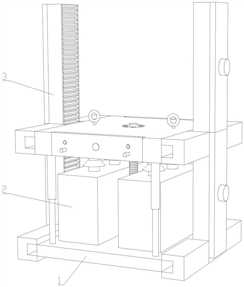
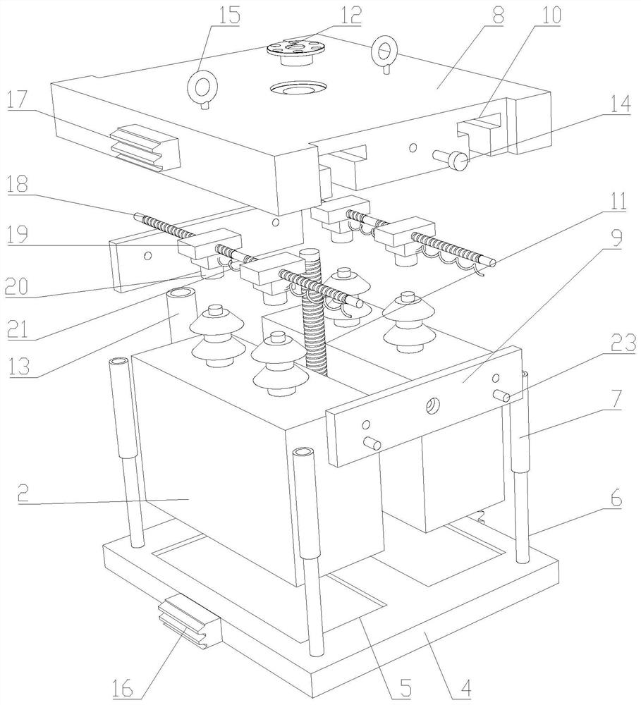
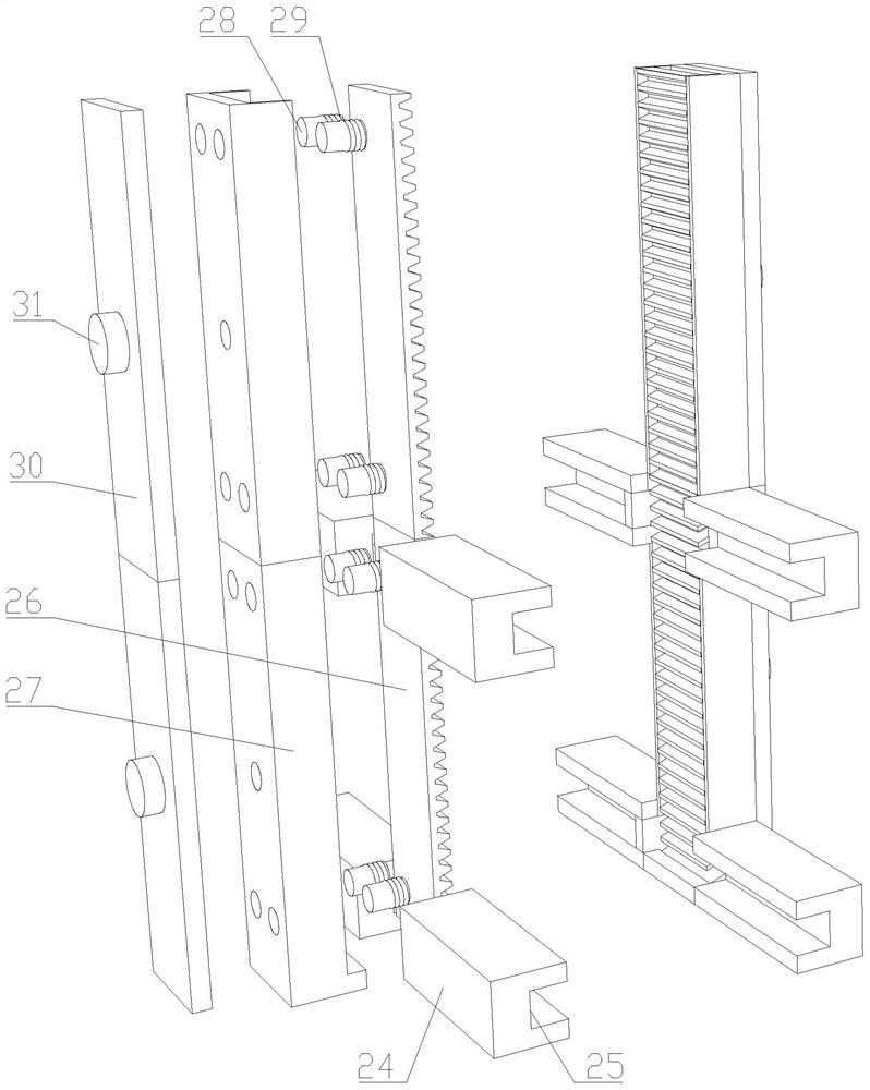
[0029] Such as Figure 1-4 As shown, the capacitor protection device proposed by the present invention includes a mounting base 1, a capacitor 2 and a mounting frame 3;

[0030] The capacitor 2 is slidably arranged on the mounting seat 1 and fixed and locked by the mounting seat 1, and the mounting seat 1 is arranged on the mounting frame 3; wherein, the mounting seat 1 includes a support plate 4, a fixing column 6, a fi...


PUM


Abstract

The capacitor protection device comprises a mounting seat, a capacitor and a mounting rack, the capacitor is slidably arranged on the mounting seat and is fixedly locked through the mounting seat; the fixing sleeve is arranged on the top plate and is in sliding connection with the fixing column; the threaded rod is arranged on the bearing and is in threaded connection with the threaded sleeve; the first locking screw penetrates through the baffle and is in threaded connection with the top plate; the two-way threaded rod is rotationally arranged on the baffle, and the T-shaped sliding block is arranged on the top plate in a sliding mode and is in threaded connection with the two-way threaded rod. The wiring sleeve is in threaded connection with the T-shaped sliding block; the wire is arranged on the connector and penetrates through the T-shaped sliding block to be electrically connected with the wiring sleeve. The rack is slidably arranged on the fixed plate; the spring is sleeved on the guide column and is propped against the fixed plate and the rack; the movable pressing plate is arranged on the guide columns, and the second locking screw penetrates through the movable pressing plate and is in threaded connection with the fixing plate. Capacitors of different heights can be installed, and the application range is wide. The wiring sleeve well protects the joint of the capacitor from corrosion and weathering, prolongs the service life, and is simple and convenient to operate.

Description

technical field [0001] The invention relates to the technical field of capacitor protection equipment, in particular to a capacitor protection device. Background technique [0002] Parallel capacitors, formerly known as phase-shifting capacitors; mainly used to compensate the reactive power of inductive loads in power systems to increase power factor, improve voltage quality, and reduce line losses. Single-phase parallel capacitors are mainly composed of cores, shells, and outlet structures. It consists of metal foil and insulating paper or plastic film stacked and wound together. A number of components, insulating parts and fasteners are press-fitted to form a capacitor core and impregnated with insulating oil; the lead wires of the capacitor plates are connected in series and in parallel. Lead to the outlet connection piece at the lower end of the outlet porcelain sleeve, and the metal shell of the capacitor is filled with insulating medium oil. Shunt capacitors are gener...

Claims


Application Information

Patent Timeline
Patent Type & Authority Applications(China)
IPC IPC(8): H01G4/228H01G4/002H01G2/12H01G2/04
CPCH01G4/228H01G2/04H01G2/12H01G4/002
Inventor 周福敬
Owner 杭州绿中游智能科技有限公司
Why Eureka
Try Eureka