Pressure flow meter and fluid control device

A fluid control device and fluid control valve technology, applied in flow control, flow control using electrical devices, measuring devices, etc., can solve problems such as changes in flow characteristics of fluid resistance elements, inability to fully press sealing parts, and deformation of fluid resistance elements, etc. To achieve the effect of improving sealing

Pending Publication Date: 2022-03-11
HORIBA STEC CO LTD
View PDF1 Cites 0 Cited by
  • Summary
  • Abstract
  • Description
  • Claims
  • Application Information

AI Technical Summary

Problems solved by technology

[0004] However, due to the thickness tolerance of the sheet-shaped sealing member or the tolerance of the fluid resistance element or the block, there are cases where the sealing member cannot be sufficiently pressed, and thus the desired sealing performance cannot be obtained.
In addition, in order to improve the sealing performance, it is conceivable to increase the force of pressing the sheet-shaped sealing member, but if this is done, the fluid resistance element will be deformed, resulting in changes in the flow characteristics of the fluid resistance element

Method used


Image

  • Pressure flow meter and fluid control device
  • Pressure flow meter and fluid control device
  • Pressure flow meter and fluid control device

Examples


Embodiment Construction

[0044] Hereinafter, a fluid control device (mass flow controller) according to one embodiment of the present invention will be described with reference to the drawings.

[0045]

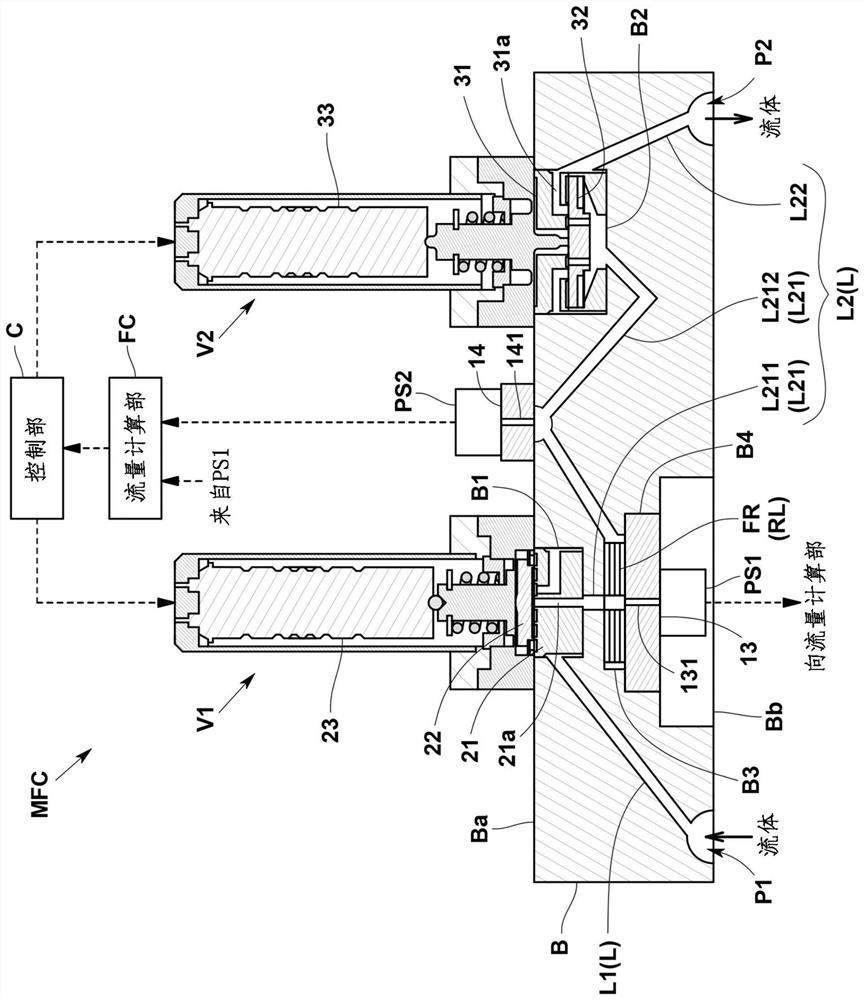
[0046] Such as figure 1 As shown, the fluid control device MFC of this embodiment is a pressure type. Specifically, the fluid control device MFC includes: a block B, in which a flow channel L for fluid flow is formed; a fluid resistance element FR, provided on the flow channel L of the block B; an upstream side pressure sensor PS1, provided at Block B is used to detect the upstream side pressure of the fluid resistance element FR; the downstream side pressure sensor PS2 is installed on the block B to detect the downstream side pressure of the fluid resistance element FR; the first fluid control valve V1 is located in the flow channel of the block B L is provided on the upstream side of the fluid resistance element FR; and a control part C performs feedback control on the first fluid control valve ...


PUM


Abstract

The present invention provides a pressure-type flow meter and a fluid control device, the pressure-type flow meter comprising: a fluid resistance element (FR) provided in a flow path (L) through which a fluid flows, the fluid resistance element (FR) having a resistance flow path (RL) formed therein, the resistance flow path (RL) communicating with the flow path (L); an upstream-side pressure sensor (PS1) that detects the upstream-side pressure of the fluid resistance element (FR); and a downstream-side pressure sensor (PS2) that detects the downstream-side pressure of the fluid resistance element (FR), the fluid resistance element (FR) is sandwiched and fixed by a pair of sandwiching members (41, 42), sheet-like sealing members (51, 52) are provided between the fluid resistance element (FR) and the sandwiching members (41, 42), and protrusions (61, 62) that partially press the sealing members (51, 52) are formed on at least one of the fluid resistance element (FR) and the sandwiching members (41, 42).

Description

technical field [0001] The present invention relates to pressure flow meters and fluid control devices. Background technique [0002] As shown in Patent Document 1, in a flow control device (mass flow controller) using a conventional pressure type flowmeter, an element formed by laminating a plurality of thin plates is used as a fluid resistance element provided in a flow path. The fluid resistance element is clamped and fixed by a pair of clamping members from its lamination direction. [0003] Here, in order to prevent fluid leakage, a sheet-shaped sealing member (for example, a thickness of 500 μm or less) is provided between each of the pair of holding members and the fluid resistance element. Furthermore, the sheet-shaped sealing member is pressed by the planar opposing surfaces of the holding member and the fluid resistance element to seal between them. [0004] However, due to the thickness tolerance of the sheet-shaped sealing member or the tolerance of the fluid r...

Claims


Application Information

Patent Timeline
Patent Type & Authority Applications(China)
IPC IPC(8): G01F1/34G01F15/00G05D7/06
CPCG01F1/34G01F15/005G05D7/0641G01F1/363G05D7/0647G01F1/586G05D7/06F16J15/06G01F1/42G01F1/12
Inventor 堀口博史安田忠弘长井健太郎
Owner HORIBA STEC CO LTD
Why Eureka
Try Eureka