
Three-dimensional measurement method and system for modulating three-dimensional code at periodic edge

A three-dimensional measurement and edge technology, which is applied in the direction of measuring devices, instruments, and optical devices, can solve the problems of increasing unwrapping time, low precision of phase unwrapping, and low precision of phase unwrapping, achieving high efficiency of point cloud reconstruction, The effect of fewer fringe patterns and faster phase resolution

Active Publication Date: 2022-03-29
GUANGDONG UNIV OF TECH
View PDF15 Cites 0 Cited by
  • Summary
  • Abstract
  • Description
  • Claims
  • Application Information

AI Technical Summary

Problems solved by technology

The spatial phase unwrapping method requires a small number of projection patterns and can be used for dynamic scene measurement, but the accuracy of phase resolution is relatively low; although the stereo phase unwrapping method can solve the problem of low accuracy of spatial phase unwrapping, it needs to add additional Camera device assisted unwrapping
The time phase unwrapping method is widely used because of its advantages of high precision, strong robustness, wide adaptability, and simple equipment. Need to project a large number of fringe patterns, increase the time to understand the package, and be sensitive to the movement of the object to be measured

Method used


Image

  • Three-dimensional measurement method and system for modulating three-dimensional code at periodic edge
  • Three-dimensional measurement method and system for modulating three-dimensional code at periodic edge
  • Three-dimensional measurement method and system for modulating three-dimensional code at periodic edge

Examples


Embodiment Construction

[0120] The technical solutions of the present invention will be further described below in conjunction with the accompanying drawings and through specific implementation methods.

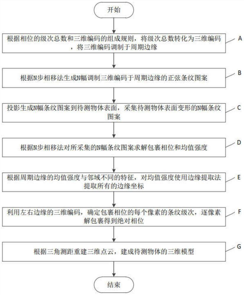
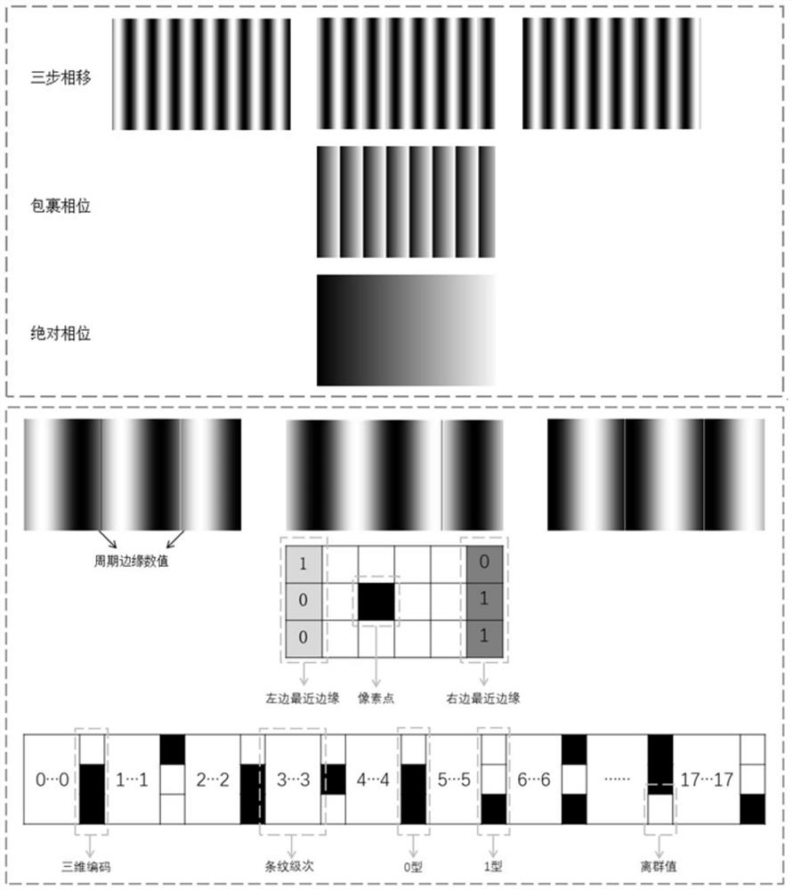
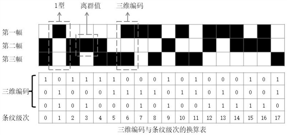
[0121] The present invention proposes a three-dimensional measuring method in which modulated three-dimensional coding is applied to the periodic edge. Based on the coding method, the modulated three-dimensional coding is integrated into the periodic edge, and N-amplitude modulated fringe patterns are generated according to the N-step phase shift method. The invention uses the N-step phase shift method to solve the wrapped phase and mean intensity. Based on the feature that the mean intensity of the periodic edge is different from that of the neighborhood, an edge detection algorithm is used to extract all edge coordinates; using the extracted edge coordinates, a three-dimensional code consisting of N fringe images for each periodic edge is obtained; for each pixel of the wrapped phase , use the thr...


PUM


Abstract

The invention discloses a three-dimensional measurement method and system for modulating a three-dimensional code at a period edge, and the method comprises the steps: A, converting the total number of levels into a three-dimensional code according to the total number of phase levels and the composition rule of the three-dimensional code, and modulating the three-dimensional code at the period edge; b, according to an N-step phase shift method, generating N stripe patterns which modulate three-dimensional codes at the edge of a period; c, projecting to generate N fringe patterns to the surface of the to-be-measured object, and collecting the deformed N fringe patterns on the surface of the to-be-measured object; d, solving wrapped phases and mean value intensity of the N fringe patterns according to an N-step phase shift method; e, extracting all edge coordinates of the mean value intensity according to different features of the mean value intensity and the neighborhood; f, determining the fringe level of each pixel wrapping the phase by using the three-dimensional codes of the left and right edges, and unwrapping pixel by pixel to obtain an absolute phase; and G, reconstructing a three-dimensional point cloud according to triangulation ranging, and establishing a three-dimensional model of the object to be measured.

Description

technical field [0001] The invention relates to the technical field of optical three-dimensional measurement, in particular to a three-dimensional measurement method and system for modulating a three-dimensional code on a periodic edge. Background technique [0002] Structured light measurement technology has the advantages of non-contact, full-field lossless measurement, high precision, and fast speed. It has been widely used in industrial inspection, machine vision, digitalization of cultural relics, and medicine. Among the existing structured light measurement systems, the structured light 3D measurement system consisting of a camera and a projector is widely used because of its simple structure and high efficiency of point cloud reconstruction. In a typical single-camera structured light 3D measurement system, the projection device projects the fringe pattern onto the surface of the measured object during the measurement process. After processing, the phase information ...

Claims


Application Information

Patent Timeline
IPC IPC(8): G01B11/25
CPCG01B11/254G01B11/2513G01B11/2527
Inventor 高健郑卓鋆张揽宇邓海祥陈云陈新
Owner GUANGDONG UNIV OF TECH
Learn More