Efficient conveying device for automatic assembly line

A technology of conveying device and assembly line, which is applied to conveyor objects, transportation and packaging, etc., can solve the problems of increased use cost, increased plant height, and invariable direction, and achieves the effect of reducing the cost of product diversion.

Pending Publication Date: 2022-04-01
GUANGDONG POWER GRID CO LTD
View PDF0 Cites 0 Cited by
  • Summary
  • Abstract
  • Description
  • Claims
  • Application Information

AI Technical Summary

Problems solved by technology

[0002] At present, in the automatic assembly line, efficient conveying units are very necessary. When conveying and diverting traditional conveyor belts, most of them cannot change direction, and divert them through height differences. When the types of products that need to be increased, the types of products that need to be diverted More, increase the diversion line by superimposing the height of the conveyor belt, and increase the overall height of the pipeline, resulting in a larger diversion area that needs to increase the height of the factory building to meet the needs of product diversion, resulting in a greatly increased cost of use

Method used


Image

  • Efficient conveying device for automatic assembly line
  • Efficient conveying device for automatic assembly line
  • Efficient conveying device for automatic assembly line

Examples


Embodiment Construction

[0029] The specific implementation manners of the present invention will be further described in detail below in conjunction with the accompanying drawings and embodiments. The following examples are used to illustrate the present invention, but are not intended to limit the scope of the present invention.

[0030] In describing the present invention, it should be understood that the terms "upper", "lower", "front", "rear", "left", "right", "vertical", "horizontal", The orientations or positional relationships indicated by "top", "bottom", "inner", "outer", etc. are based on the orientations or positional relationships shown in the drawings, and are only for the convenience of describing the present invention and simplifying the description, rather than indicating or implying the It should not be construed as limiting the invention that a device or element must have a particular orientation, be constructed, and operate in a particular orientation.

[0031] In the description ...


PUM


Abstract

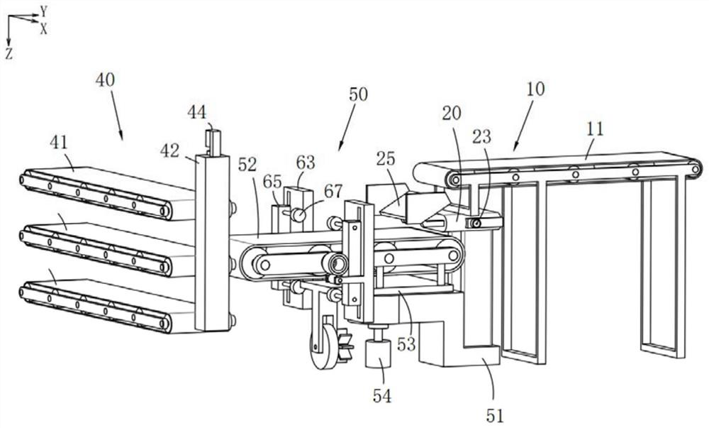
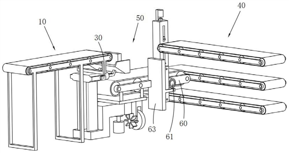
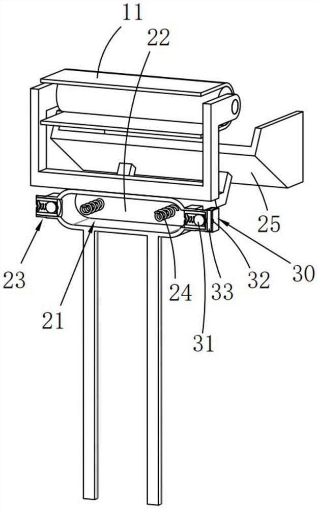
The invention relates to the technical field of conveying equipment, and discloses an efficient conveying device for an automatic assembly line, which comprises at least one conveying input mechanism, at least two shunting conveying mechanisms and a transfer conveying mechanism, the transfer conveying mechanism comprises a rotating support and a transfer conveying belt, and the rotating support is provided with a rotating driving part; the transfer conveyor belt is rotationally mounted on the rotary support around the Z-axis direction; the rotary driving part is in driving connection with the transfer conveyor belt; the conveying input mechanism comprises an input conveying belt, the transfer conveying belt is located below the input conveying belt, and the output end of the input conveying belt is arranged along an input rotation track formed by rotation of the input end of the transfer conveying belt. The input ends of the shunting conveying belts are arranged at intervals along an output rotation track formed by rotation of the output end of the transfer conveying belt. According to the efficient conveying device for the automatic assembly line, the flow dividing direction of the assembly line can be changed, product flow dividing conveying lines are added, and the product flow dividing cost is reduced.

Description

technical field [0001] The invention relates to the technical field of conveying equipment, in particular to an efficient conveying device for an automatic assembly line. Background technique [0002] At present, in the automatic assembly line, efficient conveying units are very necessary. When conveying and diverting traditional conveyor belts, most of them cannot change direction, and divert them through height differences. When the types of products that need to be increased, the types of products that need to be diverted More, the diversion line is increased by superimposing the height of the conveyor belt, and the overall height of the assembly line is increased. As a result, the larger diversion area needs to increase the height of the factory building to meet the needs of product diversion, resulting in a greatly increased use cost. Contents of the invention [0003] The purpose of the present invention is to provide a high-efficiency conveying device for an automat...

Claims


Application Information

Patent Timeline
IPC IPC(8): B65G47/64
CPCY02P90/02
Inventor 彭策招景明唐捷杨亮明刘海斌黄家嘉张永旺危阜胜吴敏王博
Owner GUANGDONG POWER GRID CO LTD
Why Eureka
Try Eureka