
Two-stage sulfide wastewater degradation device based on hydrodynamic cavitation
A wastewater degradation device and a technology of hydrodynamic cavitation, applied in the field of pollutant degradation, can solve the problems of low efficiency, hydrogen sulfide gas emission, and inapplicability, and achieve the effects of high efficiency, large processing capacity and convenient operation.
- Summary
- Abstract
- Description
- Claims
- Application Information
AI Technical Summary
Problems solved by technology
Method used
Image

Examples
Embodiment Construction
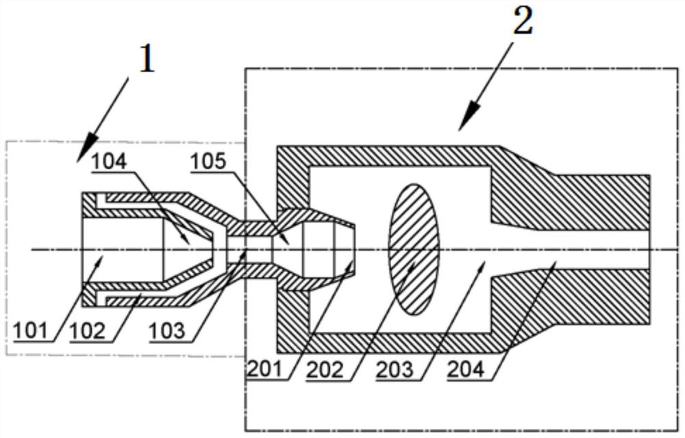
[0037] The double-stage degradation device for sulfide wastewater based on hydraulic cavitation of the present invention, such as figure 1 As shown, it includes a cavitation jet tube 1 and a reaction chamber 2. One end of the cavitation jet tube 1 is provided with a liquid inlet 101 and an oxidant channel 102, and the other end is provided with a nozzle 201. The inside of the cavitation jet tube 1 is located at the liquid inlet. A throat 103 is provided between the nozzle 101 and the nozzle 201 . The liquid inlet 101, the oxidant channel 102 and the throat 103 form a mixing zone. Between the liquid inlet 101 and the throat 103 is a tapered incident section 104 that shrinks along the direction of liquid flow. A tapered exit section 105 is provided between the nozzle 201 and the throat 103, expanding along the liquid flow direction.
[0038] The oxidant channel 102 is arranged in the side wall of the cavitation jet tube 1 and is connected to the throat 103. The inner diameter ...
PUM
 Abstract
Description
Claims
Application Information