
Double-sided stamping high-precision positioning edge banding machine

A high-precision, edge-banding machine technology, used in household components, wood processing appliances, other plywood/plywood appliances, etc., can solve the problems of the inability to adjust the size of the edge-banding, the edge-sealing tape stuck inside the device, and the limitations are large. , to improve the quality of edge sealing, improve the effect of edge sealing, and save costs.

Pending Publication Date: 2022-04-08
李舟
View PDF4 Cites 0 Cited by
  • Summary
  • Abstract
  • Description
  • Claims
  • Application Information

AI Technical Summary

Problems solved by technology

[0002] In the traditional furniture production industry, traditional edge banding machines are often used to manually band the furniture, making the furniture more beautiful and practical under the premise of ensuring quality. However, the traditional edge banding machine has the problem that the size of the edge banding cannot be adjusted, which has great limitations. , and the traditional edge banding machine also has the problem that the edge banding strip is stuck inside the device. Therefore, it is necessary to design a double-sided stamping high-precision positioning edge banding machine with adaptive diameter and adaptive width

Method used


Image

  • Double-sided stamping high-precision positioning edge banding machine
  • Double-sided stamping high-precision positioning edge banding machine
  • Double-sided stamping high-precision positioning edge banding machine

Examples


Embodiment Construction

[0027] The following will clearly and completely describe the technical solutions in the embodiments of the present invention with reference to the accompanying drawings in the embodiments of the present invention. Obviously, the described embodiments are only some, not all, embodiments of the present invention. Based on the embodiments of the present invention, all other embodiments obtained by persons of ordinary skill in the art without making creative efforts belong to the protection scope of the present invention.

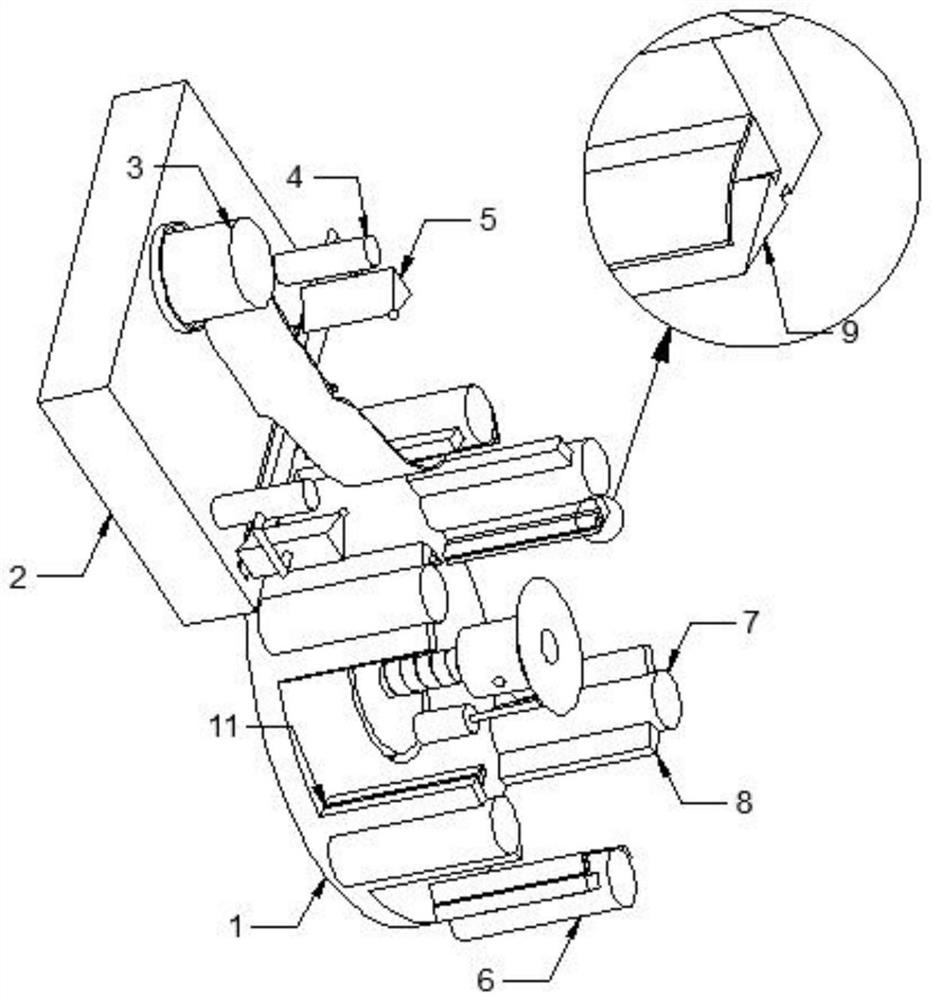
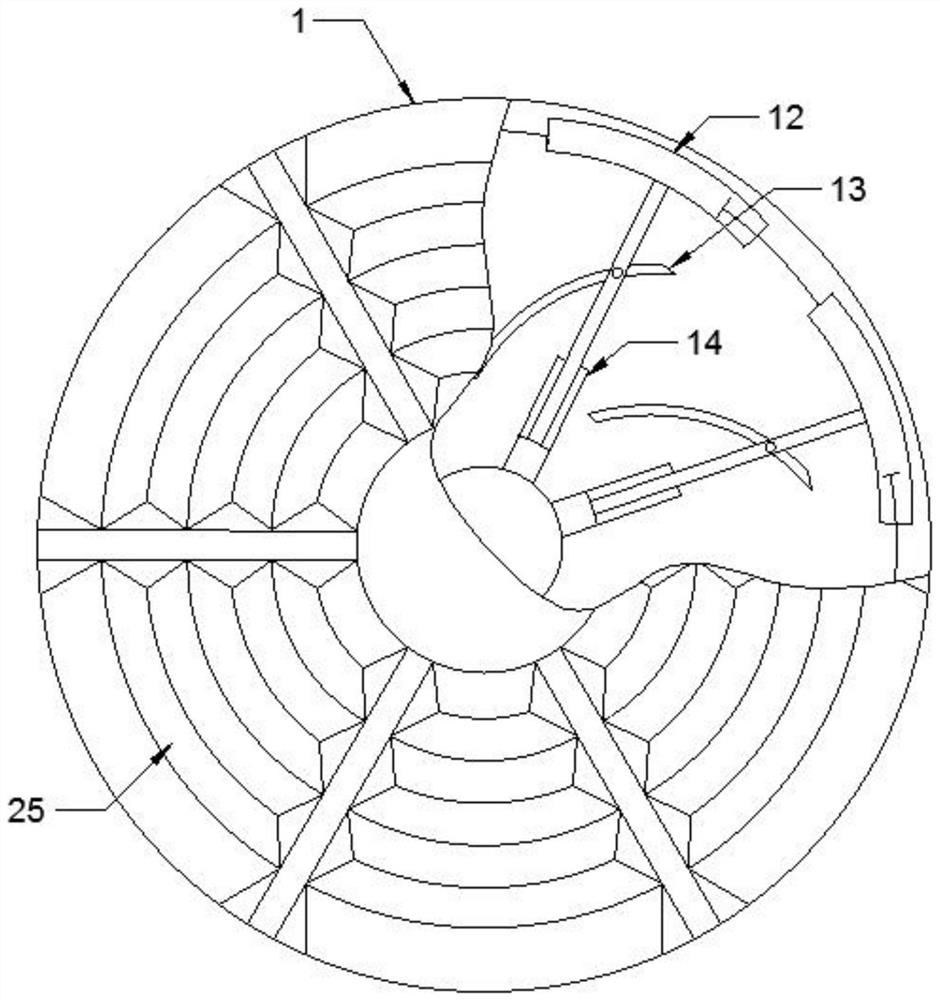
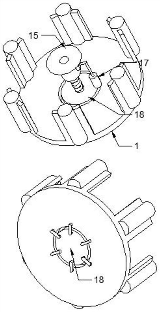
[0028] see Figure 1-5 , the present invention provides a technical solution: a double-sided stamping high-precision positioning edge banding machine, including a main frame 1, a fixing mechanism 15 is arranged inside the main frame 1, a trimming mechanism 11 is arranged on the periphery of the main frame 1, and one side of the main frame 1 runs through The auxiliary machine 2 is connected, and the upper end of the auxiliary machine 2 is provided with an edge ...


PUM


Abstract

The invention discloses a double-sided stamping high-precision positioning edge sealing machine which comprises a main machine table and is characterized in that a fixing mechanism is arranged in the main machine table, a trimming mechanism is arranged on the periphery of the main machine table, an auxiliary machine table is connected to one side of the main machine table in a penetrating mode, and an edge sealing mechanism is arranged at the upper end of the auxiliary machine table; air holes are formed in the lower end of the fixing mechanism, the interior of the fixing mechanism is hollow, threads are arranged on the inner wall of the fixing mechanism, a limiting rod is welded to one side of the lower end of the fixing mechanism, a limiting guide sleeve is connected to the periphery of the limiting rod in a sleeving mode, an inner machine table is arranged below the fixing mechanism, and a threaded column is welded to the upper end of the inner machine table; a folding bag is arranged in the main machine table, a plurality of annular sleeves are arranged on the periphery of the interior of the main machine table, clamping rods are welded to one ends of the annular sleeves, and the annular sleeves are connected in pairs through the clamping rods.

Description

technical field [0001] The invention relates to the technical field of edge banding machines, in particular to a double-sided stamping high-precision positioning edge banding machine. Background technique [0002] In the traditional furniture production industry, traditional edge banding machines are often used to manually band the furniture, making the furniture more beautiful and practical under the premise of ensuring quality. However, the traditional edge banding machine has the problem that the size of the edge banding cannot be adjusted, which has great limitations. , and the traditional edge banding machine also has the problem that the edge banding strip is stuck inside the device. Therefore, it is necessary to design a double-sided stamping high-precision positioning edge banding machine with adaptive diameter and adaptive width. Contents of the invention [0003] The purpose of the present invention is to provide a double-sided stamping high-precision positioning...

Claims


Application Information

Patent Timeline
Patent Type & Authority Applications(China)
IPC IPC(8): B27N7/00
CPCB27N7/00B27D5/00B27G1/00
Inventor 李舟
Owner 李舟
Learn More