
Dynamic load weighing module

A weighing module and dynamic load technology, applied in the field of weighing sensors, can solve problems such as affecting the measurement and weighing accuracy, sensor damage, and inability to guarantee the weighing accuracy.

Pending Publication Date: 2022-04-08
中航电测仪器(西安)有限公司
View PDF0 Cites 0 Cited by
  • Summary
  • Abstract
  • Description
  • Claims
  • Application Information

AI Technical Summary

Problems solved by technology

These reaction kettles and mixing tanks generally have a stirring function, which will inevitably generate internal stirring force, and the use of the motor will also cause vibration. If the material tank exists in an outdoor environment, it may also be affected by uncontrollable external forces such as wind load and air flow. These factors will affect to the accuracy of weighing
[0003] The existing traditional weighing module includes upper plate, sensor, lower base plate, load-bearing bolts, etc. This structural product is weighed through rigid force-transmitting parts, and its advantage is that it can adapt to the on-site material tank by adjusting the height of the bolts. Supporting legs, but the disadvantages are also more obvious: the weighing accuracy can be guaranteed only when it is subjected to vertical force, but when it is subjected to horizontal force and lateral force, the weighing accuracy cannot be guaranteed
When the lateral force is too large, it may also cause damage to the sensor

Method used


Image

  • Dynamic load weighing module
  • Dynamic load weighing module
  • Dynamic load weighing module

Examples


Embodiment Construction

[0027] The technical solutions in the embodiments of the present invention will be clearly and completely described below in conjunction with the accompanying drawings in the embodiments of the present invention. Obviously, the described embodiments are only some of the embodiments of the present invention, not all of them; based on The embodiments of the present invention and all other embodiments obtained by persons of ordinary skill in the art without making creative efforts belong to the protection scope of the present invention.

[0028] It should be noted that the words "front", "rear", "left", "right", "upper" and "lower" used in the following description refer to the directions in the drawings, and the words "inner" and "outer ” refer to directions towards or away from the geometric center of a particular part, respectively.

[0029] Unless otherwise defined, all technical and scientific terms used herein have the same meaning as commonly understood by one of ordinary ...


PUM


Abstract

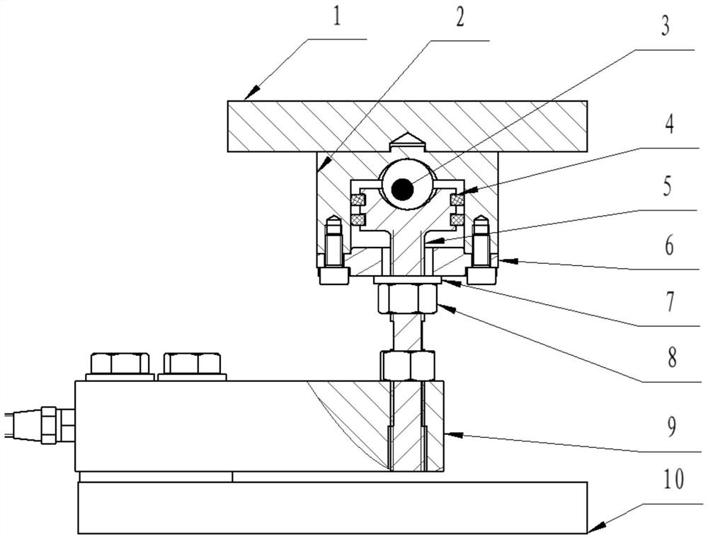
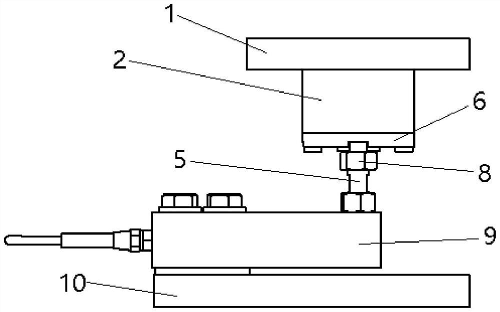
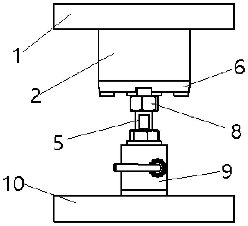
The invention discloses a dynamic load weighing module, which comprises an upper top plate, an upper ball socket, a lower ball socket bearing rod, a lower ball socket cover, a weighing sensor and a lower bottom plate, the upper ball socket is fixedly connected to the bottom of the upper top plate, a cavity is formed in the upper ball socket, the bottom of the upper ball socket is open, the top of the lower ball socket force bearing rod is located in the cavity of the upper ball socket, semicircular concave ball sockets are arranged on the top of the lower ball socket force bearing rod and the top of the cavity of the upper ball socket, and a steel ball is arranged between the two concave ball sockets. A bottom opening of the upper ball socket is connected with a lower ball socket cover, and the bottom of a lower ball socket force bearing rod is connected with a load bearing end of a weighing sensor; the diameter of the top of the lower ball socket force-bearing rod is larger than that of other parts, a downward step surface is formed between the top of the lower ball socket force-bearing rod and the other parts, and when the top of the lower ball socket force-bearing rod and the inner concave ball sockets at the top of the upper ball socket cavity are both attached to the steel ball, the step surface of the lower ball socket force-bearing rod and the top of the lower ball socket cover are arranged in a clearance mode; the fixed end of the weighing sensor is fixedly connected with the lower bottom plate, and the weighing sensor and the lower bottom plate are arranged in a spaced mode.

Description

technical field [0001] The invention belongs to the field of weighing sensors and relates to a dynamic load weighing module. Background technique [0002] In chemical industry, petroleum, metallurgy, paint and other industries, there are a large number of liquid raw materials. During the production process of these industries, the raw materials need to be weighed, measured and mixed to ensure that the finished product is qualified. These reaction kettles and mixing tanks generally have a stirring function, which will inevitably generate internal stirring force, and the use of the motor will also cause vibration. If the material tank exists in an outdoor environment, it may also be affected by uncontrollable external forces such as wind load and air flow. These factors will affect to the accuracy of weighing. [0003] The existing traditional weighing module includes upper plate, sensor, lower base plate, load-bearing bolts, etc. This structural product is weighed through ri...

Claims


Application Information

Patent Timeline
IPC IPC(8): G01G21/23G01G23/00
Inventor 巩伦庆董威路新科曹超陈立鹏刘峰雷磊周阳王瑞林方佳毅
Owner 中航电测仪器(西安)有限公司
Learn More