
Hob tool apron system loading running-in performance testing device and method

A system loading and testing device technology, which is applied in the direction of measuring devices, testing of mechanical components, testing of machine/structural components, etc., can solve problems such as differences in hob working conditions, achieve reliable performance, improve comprehensive tunneling performance, and intuitive experiments accurate effect

Active Publication Date: 2022-04-12
CENT SOUTH UNIV +2
View PDF10 Cites 3 Cited by
  • Summary
  • Abstract
  • Description
  • Claims
  • Application Information

AI Technical Summary

Problems solved by technology

[0004] The invention provides a device and method for testing the loading and running-in performance of the hob tool holder system, the purpose of which is to solve the problem that there is a difference between the existing hob running-in test and the actual hob working state

Method used


Image

  • Hob tool apron system loading running-in performance testing device and method
  • Hob tool apron system loading running-in performance testing device and method
  • Hob tool apron system loading running-in performance testing device and method

Examples


Embodiment 1

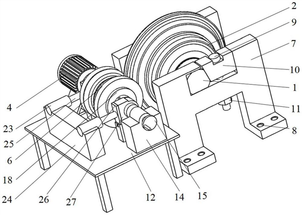
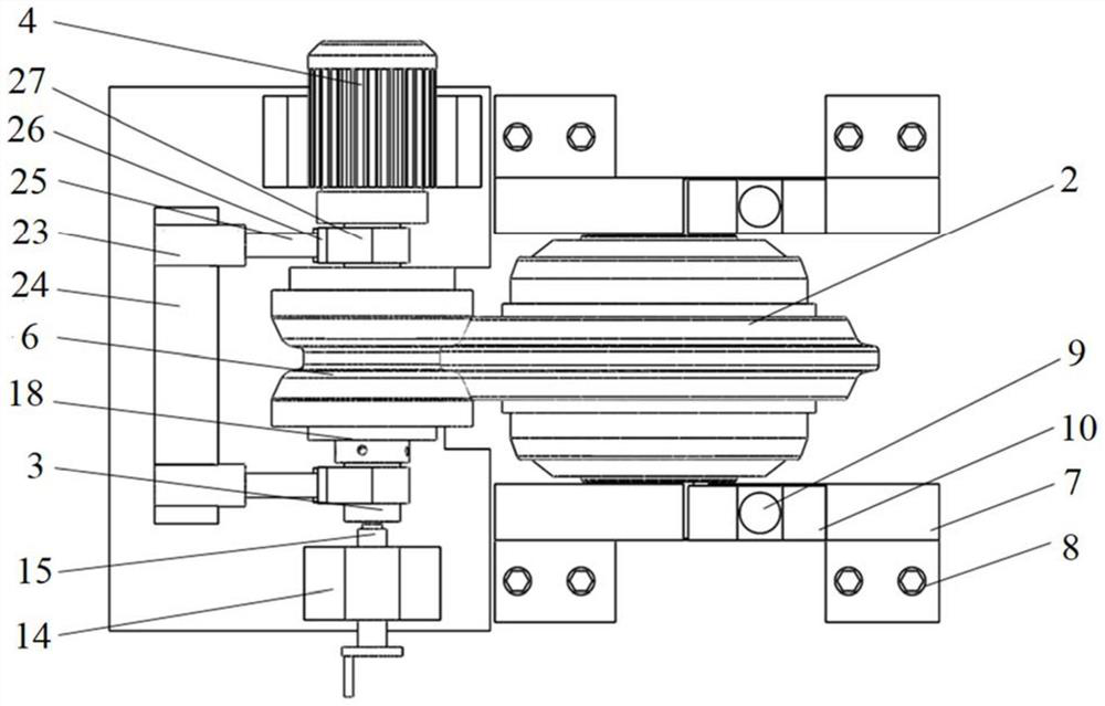
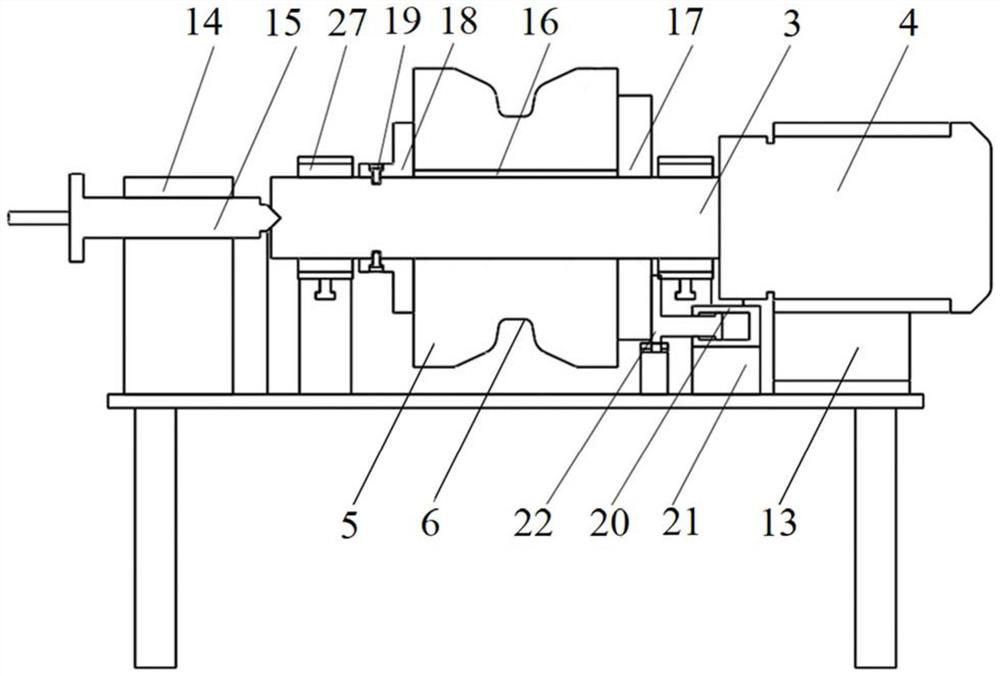
[0034] Such as Figure 1 to Figure 3 As shown, the embodiment of the present invention provides a hob tool holder system load run-in performance test device, including: a tool holder, the knife holder is used to fix the cutter shaft 1, and the hob 2 is opposite to the cutter shaft 1 Rotation setting; running-in device, the transmission shaft 3 is rotated relative to the running-in device, the transmission shaft 3 is driven by the motor 4, and the running-in contact seat 5 is coaxially arranged on the transmission shaft 3, and the running-in contact The seat 5 is provided with a running-in groove 6, the shape of the running-in groove 6 corresponds to the contour shape of the cutter ring of the hob 2, and the running-in groove 6 is used to fit the cutter ring of the hob 2; Vertical force device, the vertical force loading device is connected with the transmission shaft 3, and the vertical force device is used to adjust the vertical force applied by the run-in groove 6 to the cut...

Embodiment 2

[0046] The embodiment of the present invention also provides a method for testing the running-in performance of the hob tool holder system under load, including:

[0047] Step 1. Select the material of the contact position between the run-in groove and the cutter ring of the hob according to the construction stratum parameters to be used by the hob;

[0048] Step 2. Start the hob tool holder system and load the running-in performance test device to monitor the linear speed of the hob and the linear speed of the running-in groove;

[0049] Step 3. Calculate the difference between the linear speed of the hob and the linear speed of the running-in groove. If the linear speed of the hob is lower than the linear speed of the running-in groove, it means that the hob is slipping during the running-in test. The greater the difference between the line speed and the line speed of the running-in groove, the more obvious the slipping phenomenon. The smaller the difference, the better the ...


PUM


Abstract

The invention provides a hobbing cutter holder system loading running-in performance testing device which comprises a cutter holder used for fixedly installing a cutter shaft, and a hobbing cutter is arranged on the cutter shaft; the running-in device is provided with a transmission shaft, the transmission shaft is driven by a motor, a running-in contact seat is coaxially arranged on the transmission shaft, a running-in groove is formed in the running-in contact seat, the shape of the running-in groove corresponds to the contour shape of a cutter ring of the hobbing cutter, and the running-in groove is used for being attached to the cutter ring of the hobbing cutter; the vertical force loading device is connected with the transmission shaft and is used for adjusting the vertical force applied by the running-in groove to the hob ring of the hob; the lateral force device is connected with one side of the running-in contact seat, and lateral force is used for adjusting the magnitude of lateral force applied to a hob ring of the hob by the running-in groove; the rotating speed monitoring device is used for monitoring the rotating speed of the running-in groove and the rotating speed of the hob ring of the hob; the invention further provides a hobbing cutter holder system loading running-in performance testing method.

Description

technical field [0001] The invention relates to the field of research on the hob performance of a tunnel boring machine, in particular to a device and method for testing the loading and running-in performance of a hob tool seat system. Background technique [0002] With the planning and construction of high-speed railways and water diversion projects in my country, tunnel boring machines (TBMs) are being used more and more widely. The work of TBM mainly relies on the extrusion of hobs to break rocks. In the construction of underground and tunnel engineering, the rock conditions are complex and changeable. The hob is prone to failure due to the action of temperature and groundwater. Severe hob loss will reduce the life of the cutter head and main bearing in extreme cases, resulting in the scrapping of the cutter head or main bearing, and the long-term suspension of TBM construction. Frequent maintenance and replacement of the hob seriously reduces the efficiency of TBM cons...

Claims


Application Information

Patent Timeline
IPC IPC(8): G01M13/00
Inventor 杨妹邰召洋李彧蓼苏逢彬夏毅敏
Owner CENT SOUTH UNIV
Learn More