Machine vision optical detection system and method

A technology of optical detection and machine vision, applied in chemical instruments and methods, cleaning methods and utensils, cleaning methods using tools, etc., can solve the problems of deviation of detection results, reduce detection accuracy, etc., and achieve accurate detection results

Pending Publication Date: 2022-04-15
南京双星塑料模具有限公司
View PDF0 Cites 0 Cited by
  • Summary
  • Abstract
  • Description
  • Claims
  • Application Information

AI Technical Summary

Problems solved by technology

[0004] The purpose of the present invention is to provide a machine vision optical detection system and method, aiming to solve the problem that if there is dust on the product in the prior art, it is easy to cause deviations in the detection results of the machine vision detection system and reduce the accuracy of detection. question

Method used


Image

  • Machine vision optical detection system and method
  • Machine vision optical detection system and method
  • Machine vision optical detection system and method

Examples


Embodiment Construction

[0034] Embodiments of the present invention are described in detail below, examples of which are shown in the drawings, wherein the same or similar reference numerals designate the same or similar elements or elements having the same or similar functions throughout. The embodiments described below by referring to the figures are exemplary and are intended to explain the present invention and should not be construed as limiting the present invention.

[0035] In describing the present invention, it should be understood that the terms "length", "width", "upper", "lower", "front", "rear", "left", "right", "vertical", The orientation or positional relationship indicated by "horizontal", "top", "bottom", "inner", "outer", etc. are based on the orientation or positional relationship shown in the drawings, and are only for the convenience of describing the present invention and simplifying the description, rather than Nothing indicating or implying that a referenced device or element...


PUM


Abstract

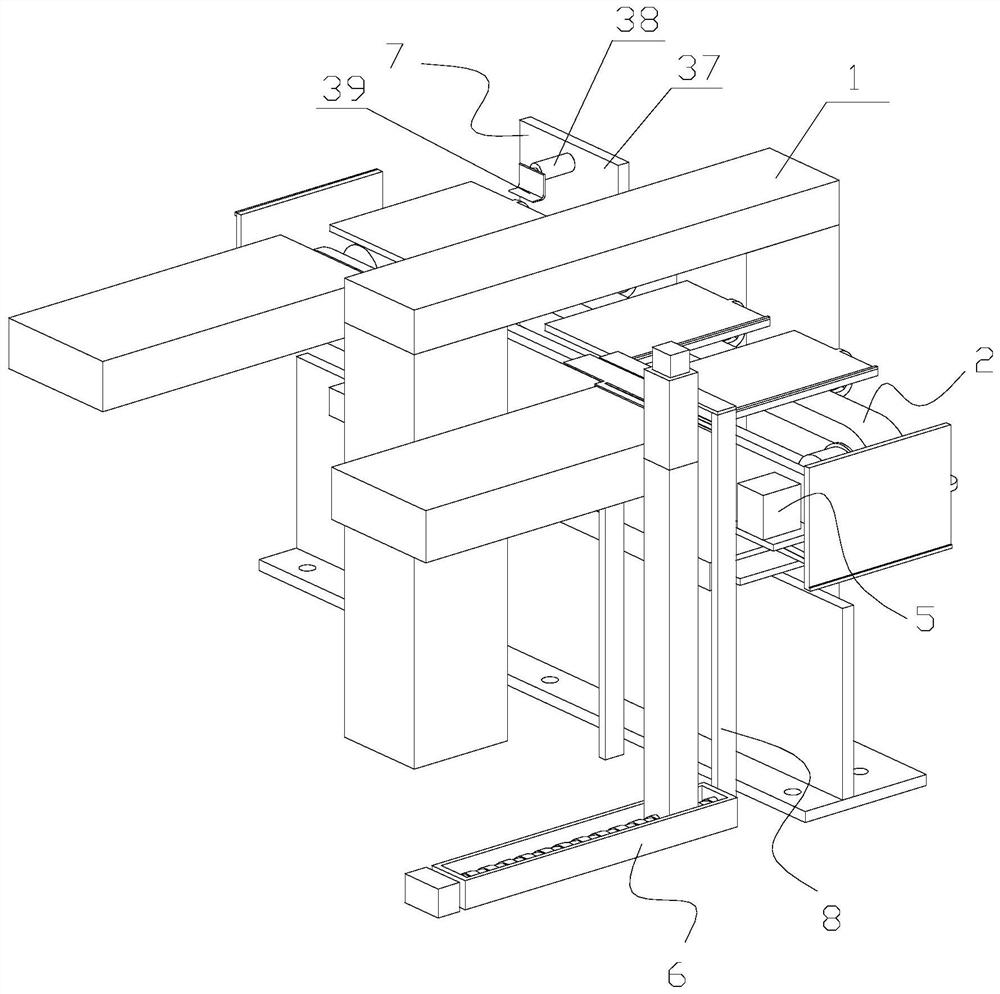
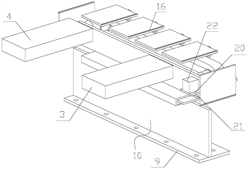
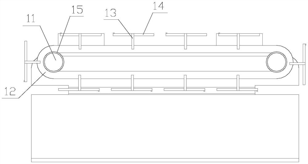
The invention relates to the technical field of detection equipment, and particularly discloses a machine vision optical detection system and method.The machine vision optical detection system comprises a vision optical detection body, a transmission mechanism, a first transmission belt, a second transmission belt, a driving assembly, a leading-in mechanism, a leading-out mechanism and a wiping mechanism; the driving assembly is arranged on one side of the transmission mechanism, the first transmission belt is arranged on one side of the transmission mechanism, the leading-in mechanism is arranged on one side of the first transmission belt, the wiping mechanism is arranged between the first transmission belt and the transmission mechanism, the second transmission belt is arranged on one side of the transmission mechanism, and the leading-out mechanism is arranged on one side of the transmission mechanism. And the guide-out mechanism and the second transmission belt are oppositely arranged. Through the arrangement of the structure, dust on the surface of the transparent plate body can be effectively cleaned, the detection result of the visual optical detection body is prevented from being influenced, and the detection result is more accurate.

Description

technical field [0001] The invention relates to the technical field of detection equipment, in particular to a machine vision optical detection system and method. Background technique [0002] At present, the existing machine vision optical inspection system has been able to detect whether there are defects in transparent plates, such as glass and acrylic plates. Therefore, machine vision optical inspection systems are often used to detect defective products in the production process of glass and acrylic plates. [0003] However, if there is dust on the product, it is easy to cause deviations in the detection results of the machine vision detection system and reduce the accuracy of detection. Contents of the invention [0004] The purpose of the present invention is to provide a machine vision optical detection system and method, aiming to solve the problem that if there is dust on the product in the prior art, it is easy to cause deviations in the detection results of the...

Claims


Application Information

Patent Timeline
Patent Type & Authority Applications(China)
IPC IPC(8): G01N21/01G01N21/892B08B1/00
Inventor 厉航天
Owner 南京双星塑料模具有限公司
Why Eureka
Try Eureka