Oral cavity reflecting device for oral cavity examination and treatment
A technology of oral cavity and movable connection, which is applied in the fields of dental mirror, application, medical science, etc. It can solve the problems of fogging on the oral mirror surface and affecting observation, and achieve the effects of improving comfort, avoiding fogging, and improving the detection and treatment environment
- Summary
- Abstract
- Description
- Claims
- Application Information
AI Technical Summary
Problems solved by technology
Method used
Image
Examples
Embodiment 1
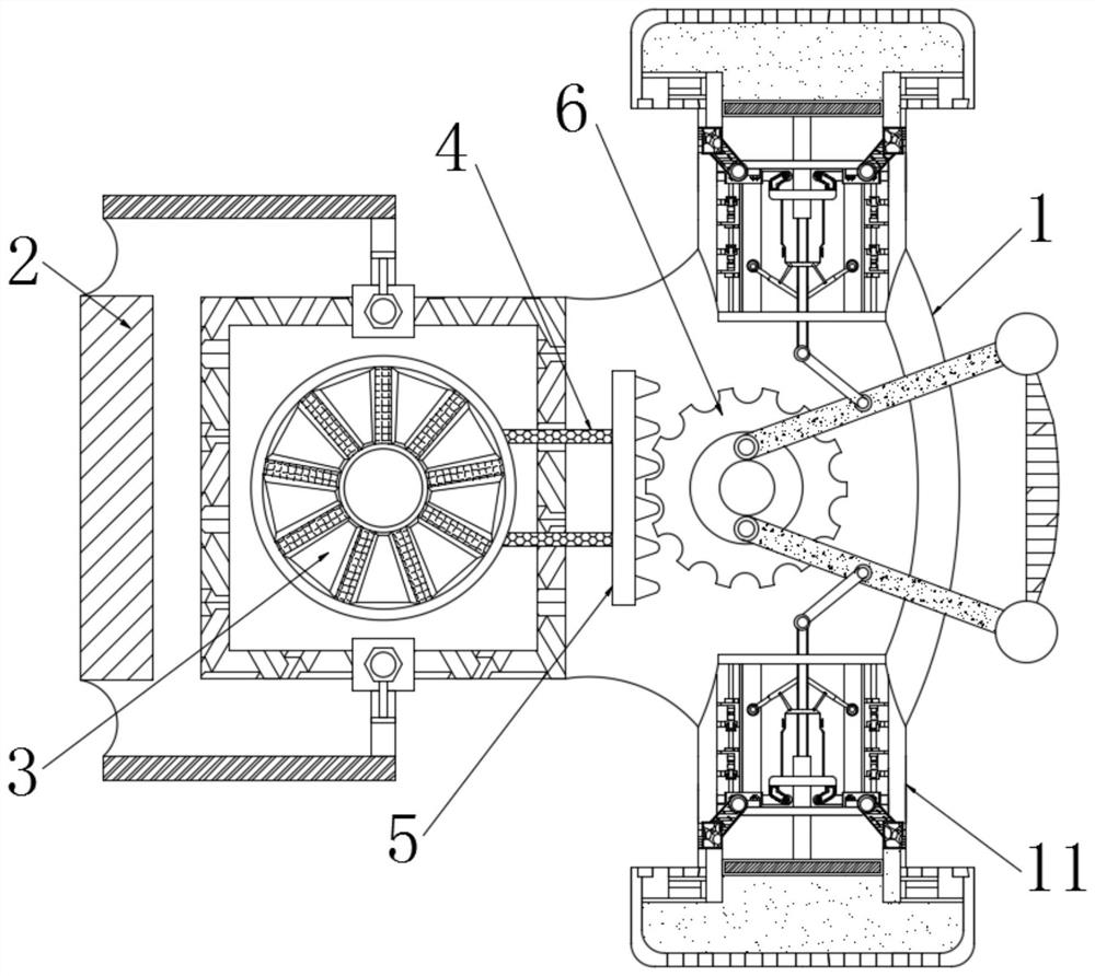
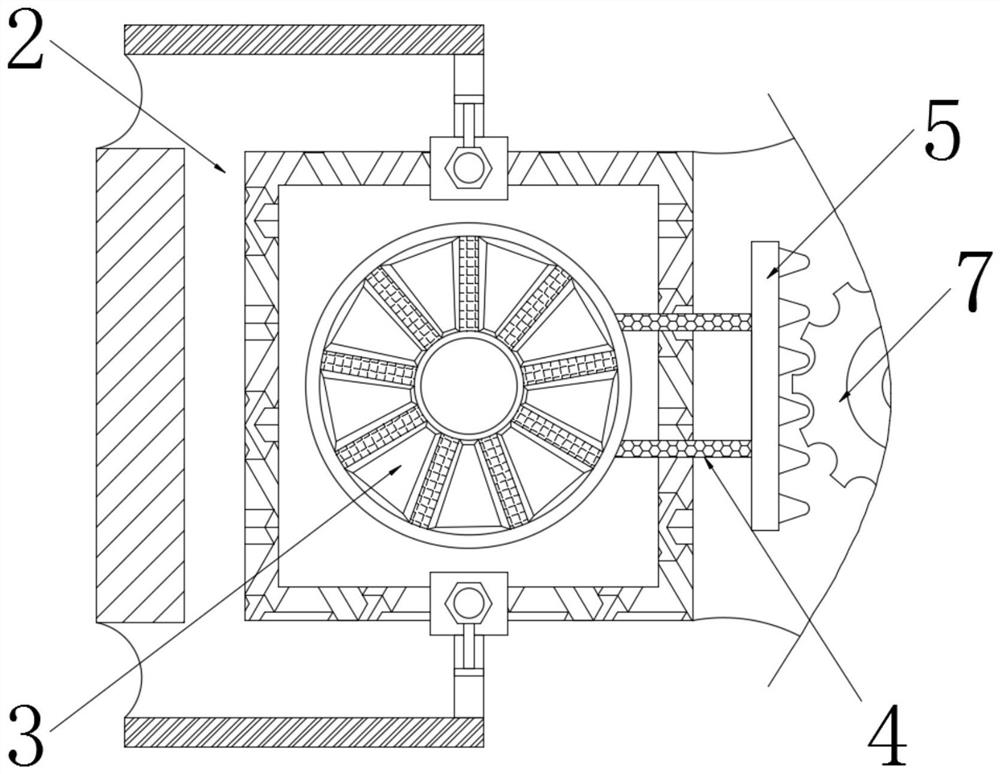
[0025] see Figure 1-3 , an oral imaging device for oral examination and treatment, comprising a mirror base 1, one end of the mirror base 1 is movably connected with a handle 2, the outer surface of the mirror base 1 and one side of the handle 2 is movably provided with a knob 3, the knob The outer surface of 3 is fixedly connected with the limit connecting rod 4, one end of the limit connecting rod 4 is fixedly connected with the tooth plate 5, and one side of the tooth plate 5 is movably connected with the lens mechanism 6, and the rotating knob 3 can be driven by the limit connecting rod 4 The tooth plate 5 rocks and moves.
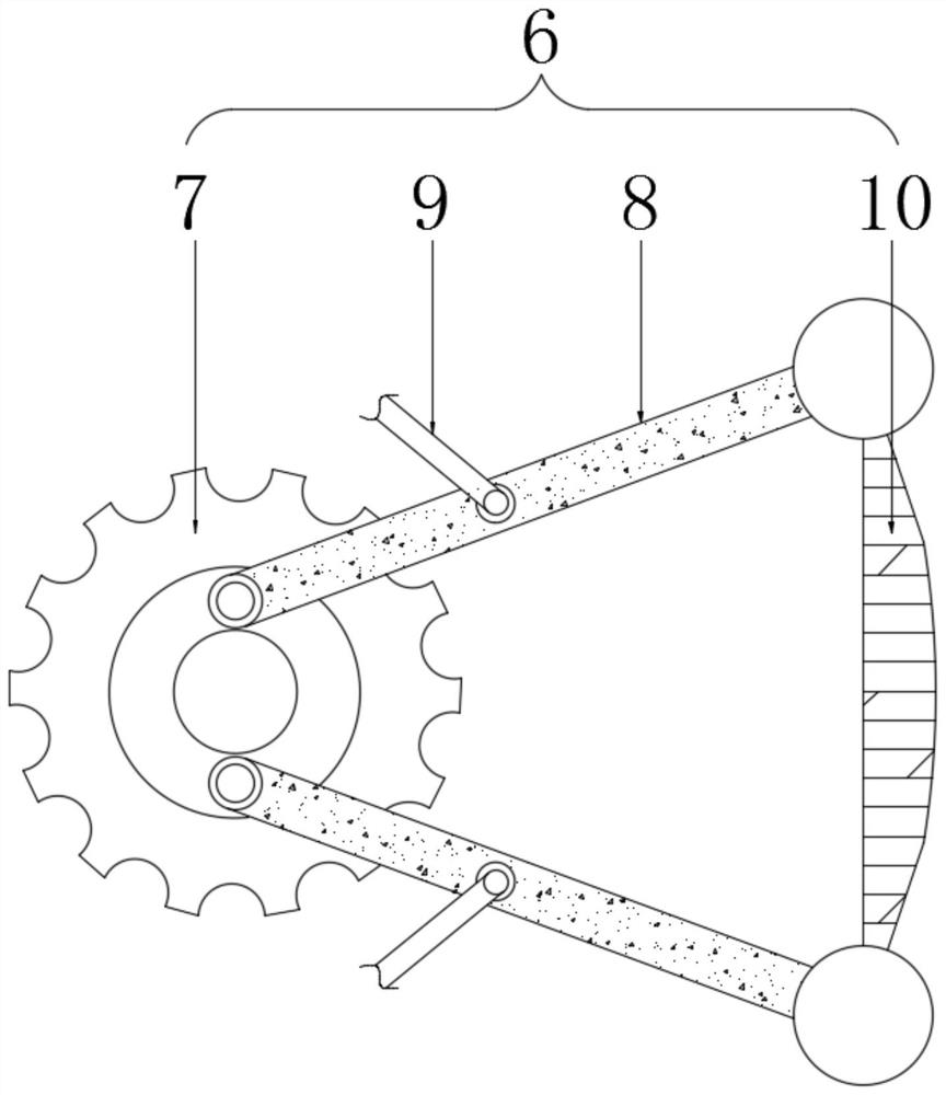
[0026] Further, the lens mechanism 6 includes a gear 7, one side of the tooth plate 5 is meshed with a gear 7, and both sides of the outer surface of the gear 7 are movably connected with a lens rod 8, and one end of the lens rod 8 is movably connected with a lens 10, and the lens rod 8 The outer surface of the outer surface is movably connected with...
Embodiment 2
[0029] see Figure 4 with Figure 5 , an oral imaging device for oral examination and treatment, comprising a mirror base 1, one end of the mirror base 1 is movably connected with a handle 2, the outer surface of the mirror base 1 and one side of the handle 2 is movably provided with a knob 3, the knob The outer surface of 3 is fixedly connected with the limit connecting rod 4, one end of the limit connecting rod 4 is fixedly connected with the tooth plate 5, and one side of the tooth plate 5 is movably connected with the lens mechanism 6, and the rotating knob 3 can be driven by the limit connecting rod 4 The tooth plate 5 rocks and moves.
[0030] Further, the side surface of the mirror base 1 and one end located at the first connecting rod 9 is movably connected with a liquid pumping mechanism 11, the liquid pumping mechanism 11 includes a sealing cover 12, the inside of the sealing cover 12 is movably connected with a first pull rod 13, and the sealing The outer surface ...
Embodiment 3
[0033] see Figure 1-5 , an oral imaging device for oral examination and treatment, comprising a mirror base 1, one end of the mirror base 1 is movably connected with a handle 2, the outer surface of the mirror base 1 and one side of the handle 2 is movably provided with a knob 3, the knob The outer surface of 3 is fixedly connected with the limit connecting rod 4, one end of the limit connecting rod 4 is fixedly connected with the tooth plate 5, and one side of the tooth plate 5 is movably connected with the lens mechanism 6, and the rotating knob 3 can be driven by the limit connecting rod 4 The tooth plate 5 rocks and moves.
[0034]Further, the lens mechanism 6 includes a gear 7, one side of the tooth plate 5 is meshed with a gear 7, and both sides of the outer surface of the gear 7 are movably connected with a lens rod 8, and one end of the lens rod 8 is movably connected with a lens 10, and the lens rod 8 The outer surface of the outer surface is movably connected with ...
PUM
 Abstract
Description
Claims
Application Information
 - R&D
- Intellectual Property
- Life Sciences
- Materials
- Tech Scout
- Unparalleled Data Quality
- Higher Quality Content
- 60% Fewer Hallucinations
Browse by: Latest US Patents, China's latest patents, Technical Efficacy Thesaurus, Application Domain, Technology Topic, Popular Technical Reports.
© 2025 PatSnap. All rights reserved.Legal|Privacy policy|Modern Slavery Act Transparency Statement|Sitemap|About US| Contact US: help@patsnap.com


