Rotational flow demulsification dehydration separation device for water-containing oil liquid

A separation device, a technology for water-containing oil, which is applied in the direction of a swirling device, a device in which the axial direction of the swirling flow can be reversed, etc., can solve problems such as poor separation effect, and achieve improved separation efficiency, increased centrifugal force, and stable internal flow field. Effect

CN114505182APending Publication Date: 2022-05-17CHONGQING TECH & BUSINESS UNIV
4 Cites 2 Cited by

Patent Information

Authority / Receiving Office
CN · China
Current Assignee / Owner
Publication Date
2022-05-17

Smart Images

  • Figure 1
    Figure 1
  • Figure 2
    Figure 2
  • Figure 3
    Figure 3
Patent Text Reader

Abstract

The invention relates to a cyclone demulsification dehydration separation device for water-containing oil liquid, which comprises a cyclone, and the opening end of a cyclone chamber in the cyclone faces an underflow pipe and is communicated with the underflow pipe through a coaxial composite curve pipe section; the large-diameter end of a concave arc transition section in the composite curve pipe section is connected with the opening end of the rotational flow chamber, the inner diameter of the large-diameter end of the concave arc transition section is equal to the inner diameter of the rotational flow chamber, the large-diameter end of a straight cone transition section is tangent to the small-diameter end of the concave arc transition section, and the small-diameter end of the straight cone transition section is tangent to the large-diameter end of a convex elliptic arc transition section. And the small-diameter end of the convex elliptic arc transition section is connected with the underflow pipe. The separation space of the cyclone is larger than that of a traditional straight-face double-cone-section cyclone and a traditional double-spherical-face smooth transition pipe section cyclone, the tangential cone angle is increased, the contact area is increased, the downward resistance of fluid is increased, a large amount of oil liquid in cyclone liquid drops is forced to migrate to an overflow opening, and the separation effect is improved. The separation effect and the separation efficiency can be obviously improved.
Need to check novelty before this filing date? Find Prior Art

Description

technical field

[0001] The invention belongs to the technical field of liquid physical separation, and in particular relates to a cyclone demulsification and dehydration separation device for water-containing oil. Background technique

[0002] The resource utilization of industrial waste oil is of great significance to national strategy, environmental protection and resource crisis relief. The primary link in the resource utilization of industrial waste oil is demulsification and dehydration. It is difficult to effectively demulsify and dehydrate the emulsion with a single treatment method. Better separation effect; Among them, the combination of electric field method and cyclone centrifugation method is more common, that is, the electric field is coupled with the cyclone centrifugal field, and the electric field intensifies the collision of liquid in the emulsion, promotes the coalescence of droplets, and increases the size of droplets The size of the swirl centrifugal fie...

Examples

Embodiment

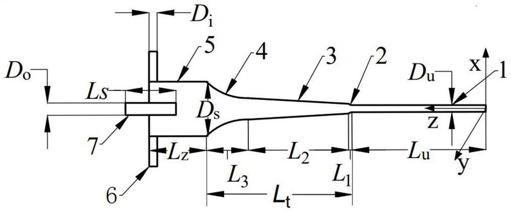
[0040] See Figure 3-Figure 5 , a cyclone demulsification dehydration separation device for water-containing oil, comprising a cyclone, the cyclone includes a cylindrical section of the cyclone chamber 5 and a bottom flow tube 1 coaxial with the cyclone chamber 5, the cyclone One end of the flow chamber 5 is open and the other end is closed. The closed end of the swirl chamber 5 is connected with an inlet pipe 6 and an overflow pipe 7 coaxial with the swirl chamber 5. The flow chamber 5 communicates, and the overflow pipe 7 insulates through the closed end of the swirl chamber 5 and communicates with the swirl chamber 5. The wall of the swirl chamber 5 and the overflow pipe 7 are all conductive materials; the open end of the swirl chamber 5 Facing the underflow pipe 1 and communicating with the underflow pipe 1 through a coaxial compound curve pipe section;

[0041]On the axial section of the swirl chamber 5, the inner wall of the compound curve pipe section includes a concav...