
A calibration stand that avoids pinching the product

A technology for calibrating tables and products, which is applied in the fields of final product manufacturing, sustainable manufacturing/processing, climate sustainability, etc., and can solve problems such as ring locking, large error in placement angle, and blocked closing of the clamping arms on the side of the calibrating table, etc. , to achieve the effect of avoiding calibration and alleviating instantaneous impact

Active Publication Date: 2022-06-28
沈阳和研科技股份有限公司
View PDF5 Cites 0 Cited by
  • Summary
  • Abstract
  • Description
  • Claims
  • Application Information

AI Technical Summary

Problems solved by technology

When there is a dimensional error in individual material sheet rings, it may cause the clamping arm on the side of the calibration table to be blocked from closing inward; Edges and corners, that is, the calibration process not only calibrates the position of the material sheet ring, but also calibrates its placement angle), during the pre-calibration clamping process of the calibration table, if the angle deviation is too large, the edges and corners of the tension ring and the side wall of the side clamp arm There may be a locking phenomenon, resulting in the obstruction of the inward closing of the clamping arms on the side of the calibration table
After being blocked, the system will control the side clamp arm to continue to apply thrust because the side clamp arm cannot move to the predetermined position. If the material in the material sheet ring is hard, brittle and too thin, the product may be damaged

Method used


Image

  • A calibration stand that avoids pinching the product
  • A calibration stand that avoids pinching the product
  • A calibration stand that avoids pinching the product

Examples


Embodiment Construction

[0034] The present invention will be described in detail below with reference to the accompanying drawings.

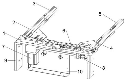
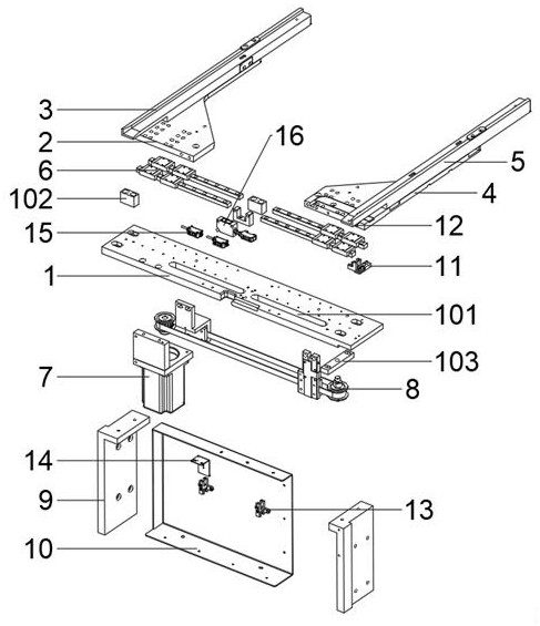
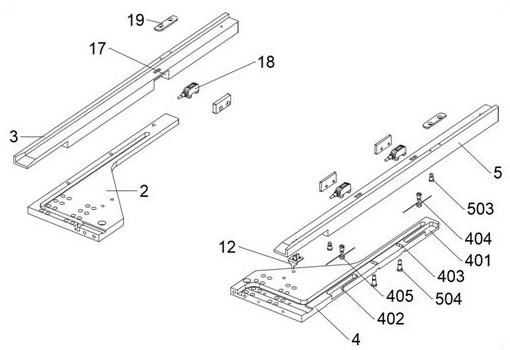
[0035] refer to Figure 1-Figure 8 , a calibration table to avoid pinching products, including base plate 1, left base plate 2, left clamp arm 3, right base plate 4, right clamp arm 5, elastic mechanism, linear sliding mechanism 6, motor 7, transmission mechanism 8, The error judgment photoelectric switch 11, the error judgment baffle 12, the fixed ends of the two linear sliding mechanisms 6 are assembled on the upper surface of the base plate 1, and the two linear sliding mechanisms 6 are symmetrical on the left and right, and the left base plate 2 and the right base plate 4 are respectively fixed and installed on the base plate 1. On the sliding ends of the two linear sliding mechanisms 6, the left clamp arm 3 is fixedly installed on the upper surface of the left base plate 2, the right clamp arm 5 is flexibly connected to the right base plate 4 through an elastic me...


PUM


Abstract

The invention belongs to the technical field of material sheet position calibration, and in particular provides a calibration table for avoiding product pinching. The calibration table mainly includes a base plate, a left base plate, a left clamp arm, a right base plate, a right clamp arm, an elastic mechanism, a linear sliding mechanism, a motor, a transmission mechanism, an error judgment photoelectric switch, and an error judgment stopper. Wherein, the elastic mechanism selects a torsion spring, and the transmission mechanism includes a driving pulley, a driven pulley, a transmission belt, a right connecting plate, a left connecting plate, and a splint. When the closing of the side clamping arm is blocked during the calibration process, the calibration table can effectively absorb the instantaneous impact caused by the side clamping arm on the material sheet ring through the elastic force of the elastic mechanism; through the error judgment photoelectric switch and the error judgment stopper, timely It is judged that the calibration operation is abnormal, and the feedback of the stop of the transmission mechanism is given. Solve the problem that when the side clamping arm is locked during the calibration process, the side clamping arm will impact the material sheet ring and continue to apply pressure subsequently, resulting in damage to the material sheet in the tension ring.

Description

technical field [0001] The invention belongs to the technical field of sheet position calibration, and particularly provides a calibration table for avoiding pinching products. Background technique [0002] The dicing machine is one of the commonly used equipment in the field of semiconductor processing, and the material pieces need to be frequently transported during its work. [0003] During the material flow process of the automatic dicing machine, it is necessary to first place the material sheet ring in the material box and place it in the feeding area, and then grab the sheet ring by the lower handling arm to the side clamping arm of the pre-calibration table. The side clamping arm moves inward to pre-calibrate the position of the sheet ring, and then the product sheet ring is transported to the work plate by the lower transport arm. After the equipment cuts the product, it is transported by the upper transport arm to the cleaning area for cleaning. After that, it is ...

Claims


Application Information

Patent Timeline
Patent Type & Authority Patents(China)
IPC IPC(8): H01L21/68H01L21/67
CPCH01L21/68H01L21/67253H01L21/67265Y02P70/50
Inventor 袁慧珠张明明王松朴宇石文徐双双
Owner 沈阳和研科技股份有限公司
Learn More