Supercharge Your Innovation With Domain-Expert AI Agents!

Joint for fiber optical cable pipeline

An optical cable connector and fiber technology, applied in the field of fiber optic cable connectors, can solve problems such as damage and difficult removal of fibers

Pending Publication Date: 2022-05-27
RELIANCE WORLDWIDE CORP (UK) LTD
View PDF13 Cites 0 Cited by
  • Summary
  • Abstract
  • Description
  • Claims
  • Application Information

AI Technical Summary

Problems solved by technology

The presence of stones can cause impacts to be transmitted directly to the ribs, causing damage
Also, over time the dirt can become compacted and thus difficult to remove when trying to visually inspect the fibers

Method used


Image

  • Joint for fiber optical cable pipeline
  • Joint for fiber optical cable pipeline
  • Joint for fiber optical cable pipeline

Examples


Embodiment Construction

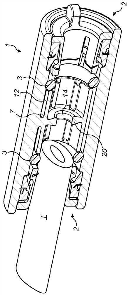
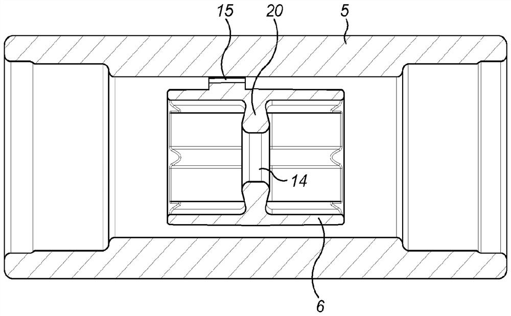
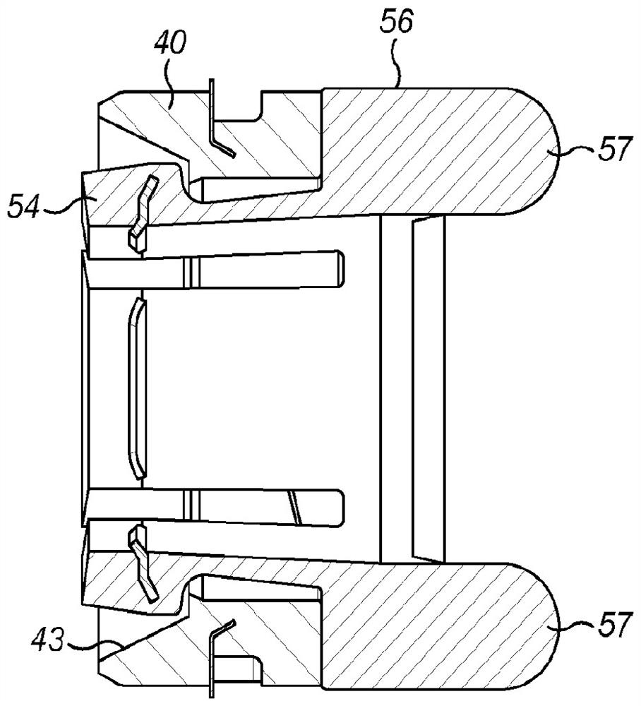
[0047] The connector includes a connector body 1 having a generally hollow cylindrical configuration centered on the main axis X. A connector 2 (described in more detail below) is provided at each end to receive and grip a tube T sealed by an O-ring 3 at each end.

[0048] The body 1 is moulded from non-opaque plastic. The plastic must be sufficiently light-transmitting that external visual inspection of the connector allows the operator to determine if a fiber optic cable or fiber bundle F is present at the center of the connector. Ideally, the body should be as close to transparent as possible. However, practical considerations mean that the ontology will not be completely transparent. Instead, the body may be translucent enough that the fibers are sufficiently visible. Suitable materials are polycarbonate, polystyrene, polyester, acrylic and nylon. The body 1 is formed during the moulding process and can optionally be polished to improve the light transmission of the bo...


PUM


Abstract

A fiber optic cable connector comprises a body (1) made of plastic defining a through hole (8) and having a connector (2) at each end for connection to a respective tube. The body comprises an outer sleeve (5) and an inner sleeve (6) configured to receive a distal end of a respective tube. The inner sleeve is spaced from the outer sleeve to define an air gap (12). The inner sleeve is supported on the outer sleeve by at least one discrete material web (7) which maintains an air gap. The outer surface of the connector body (1) is not provided with ribs.

Description

technical field [0001] The present invention relates to a fiber optic cable connector for use above or below ground level. Background technique [0002] Such connectors are used in the laying of fiber optic cables. Cables are used, for example, to provide fiber optic cable connections from junction boxes to buildings such as offices or residences in order to provide connections for Internet data. [0003] Fiber optic cables are provided in bundles of individual fibers that can be several kilometers long. Fiber bundles / cables are loaded through tubes (often referred to as conduits / micro conduits / pipes), which are typically 50 meters long, but can also be as long as 2000 meters. Therefore, multiple tubes may need to be connected together in order to support the full length of fiber bundles. [0004] Because of the way they are used, there are unique grouping requirements for fiber optic cable connectors. [0005] Its outer diameter must be as small as possible in order to ...

Claims


Application Information

Patent Timeline
IPC IPC(8): G02B6/38
CPCG02B6/381G02B6/52G02B6/4459G02B6/3887G02B6/4428
Inventor G·安塞尔J·史密斯
Owner RELIANCE WORLDWIDE CORP (UK) LTD
Features
  • R&D
  • Intellectual Property
  • Life Sciences
  • Materials
  • Tech Scout
  • Unparalleled Data Quality
  • Higher Quality Content
  • 60% Fewer Hallucinations
Learn More