Building lamp top cover stamping equipment

A technology of stamping equipment and top cover, which is applied in the field of stamping equipment for the top cover of architectural lamps, to achieve the effects of saving manpower, avoiding stamping failure, and avoiding impact

Pending Publication Date: 2022-06-17
吴志雄
View PDF0 Cites 0 Cited by
  • Summary
  • Abstract
  • Description
  • Claims
  • Application Information

AI Technical Summary

Problems solved by technology

[0005] In order to overcome the shortcomings of the existing stamping equipment for the top cover of architectural lamps that manually fix the top cover material to prevent stamping failure caused by the movement of the top cover material, a kind of architectural lamp top that can fix the top cover material and then perform stamping work is provided. Cap Stamping Equipment

Method used


Image

  • Building lamp top cover stamping equipment
  • Building lamp top cover stamping equipment
  • Building lamp top cover stamping equipment

Examples


Embodiment 1

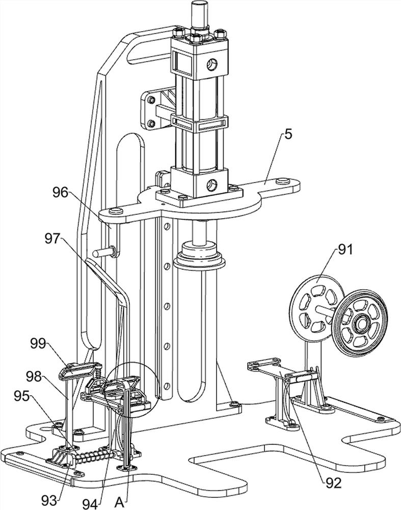
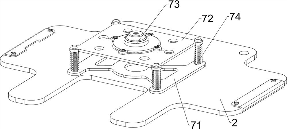
[0032] A stamping equipment for the top cover of architectural lamps, refer to figure 1 and figure 2 As shown, it includes a chassis 1, a bottom plate 2, a mounting table 3, a hydraulic cylinder 4, a first mold 5, a guide rail frame 6, a buffer mechanism 7 and a limit mechanism 8. The top of the chassis 1 is fixed with a bottom plate 2 through bolts, and the bottom plate 2 The rear side of the top is fixed with a mounting table 3 by bolts, and a hydraulic cylinder 4 is arranged on the front side of the upper part of the mounting table 3. The hydraulic cylinder 4 can provide power for the stamping work. 5. The top cover can be punched out. A guide rail frame 6 is arranged in the middle of the front side of the mounting table 3. The first mold 5 is slidably connected with the guide rail frame 6. The bottom plate 2 is provided with a buffer mechanism 7. A limiting mechanism 8 is connected, and the limiting mechanism 8 can clamp the top cover material.

[0033] refer to image...

Embodiment 2

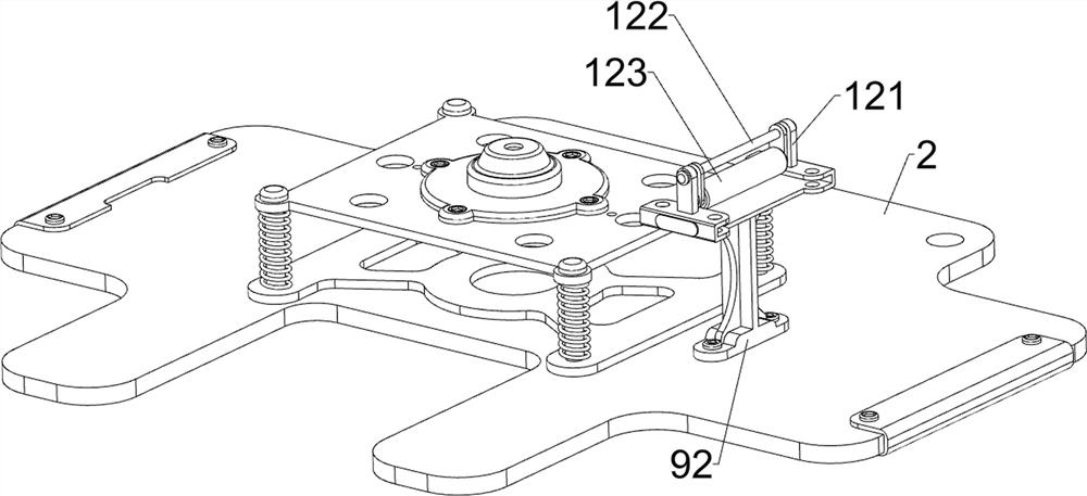
[0037] On the basis of Example 1, refer to figure 1 , Figure 5 , Image 6 and Figure 7 As shown, it also includes a feeding mechanism 9, which can feed the top cover material. The feeding mechanism 9 includes a receiving rack 91, a first guide groove plate 92, a guide seat 93, and a second guide groove. Plate 94, first return spring 95, contact post 96, first wedge plate 97, mounting bracket 98, second wedge plate 99, mounting bracket 910, clamping plate 911 and second return spring 912, the top right side of bottom plate 2 passes through The material receiving rack 91 is fixedly connected with the bolts, and the first guide groove plate 92 is fixedly connected with the top right side of the bottom plate 2 by bolts. A guide seat 93 is provided. The right side of the guide seat 93 is slidably provided with a second guide groove plate 94. Two first return springs 95 are connected between the lower left side of the second guide groove plate 94 and the left side of the guide ...


PUM


Abstract

The invention relates to top cover stamping equipment, in particular to building lamp top cover stamping equipment. According to the building lamp top cover stamping equipment, top cover materials can be fixed and then stamped. According to the technical scheme, the building lamp top cover stamping equipment comprises a machine box, a bottom plate, a mounting table, a hydraulic cylinder, a first mold and the like, the bottom plate is arranged on the front side of the top of the machine box, the mounting table is arranged on the rear side of the top of the bottom plate, and the hydraulic cylinder capable of providing power for stamping work is arranged on the front side of the upper portion of the mounting table; a first die capable of punching a top cover is arranged at the bottom of a telescopic rod of the hydraulic cylinder. And the first limiting plate and the second limiting plate are matched to clamp the top cover material, so that the top cover material cannot move, the punching failure can be avoided, and the punching work can be better carried out.

Description

technical field [0001] The invention relates to a top cover stamping device, in particular to a top cover stamping device for architectural lamps. Background technique [0002] Lamps are the general term for lighting tools, which refer to appliances that can transmit light, distribute and change the light distribution of light sources. Existing lamps generally include a shell and a top cover. During the production process of lamps, it is necessary to punch out the lamp top cover from the raw materials. [0003] The existing stamping equipment for the top cover of architectural lamps includes a chassis, a bottom plate, a mounting table, a hydraulic cylinder, a first mold and a guide rail frame. There is a hydraulic cylinder on the side, a first mold at the bottom of the telescopic rod of the hydraulic cylinder, a guide rail frame in the middle of the front side of the installation table, and the first mold is connected with the guide rail frame in a sliding manner. The top c...

Claims


Application Information

Patent Timeline
Patent Type & Authority Applications(China)
IPC IPC(8): B21D43/00B21D43/11B21D43/20B08B1/02
CPCB21D43/003B21D43/11B21D43/20B08B1/02
Inventor 吴志雄
Owner 吴志雄
Why Eureka
Try Eureka