
A punch blanking positioning device

A positioning device and punching machine technology, applied in the field of punching machine manufacturing, can solve problems such as punching failure, shaking or tilting, and affecting product quality, and achieve the effects of avoiding punching failure, simple structure, and flexible and convenient adjustment

Active Publication Date: 2016-07-20
绩溪徽腾机械有限公司
View PDF6 Cites 0 Cited by
  • Summary
  • Abstract
  • Description
  • Claims
  • Application Information

AI Technical Summary

Problems solved by technology

For example, we use switch sockets, cups, cupboards, dishes, computer cases, and even missile planes... There are many accessories that can be produced through molds with punching machines. The design principle of punching machines is to convert circular motion into linear motion. The power of the main motor drives the flywheel, and the clutch drives the gear, crankshaft (or eccentric gear), connecting rod, etc. to achieve the linear motion of the stamping parts. In the actual use of the energy-saving punching machines on the market, the stamping parts pass through the punching head at high speed. When pressing down, there will inevitably be shaking or tilting, which will lead to stamping failure and affect product quality

Method used


Image

  • A punch blanking positioning device
  • A punch blanking positioning device

Examples


Embodiment Construction

[0012] In order to make the technical means, creative features, goals and effects achieved by the present invention easy to understand, the present invention will be further described below in conjunction with specific illustrations.

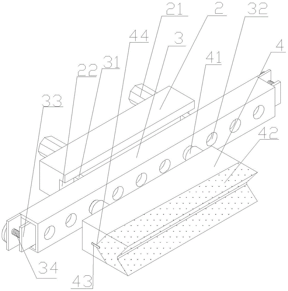
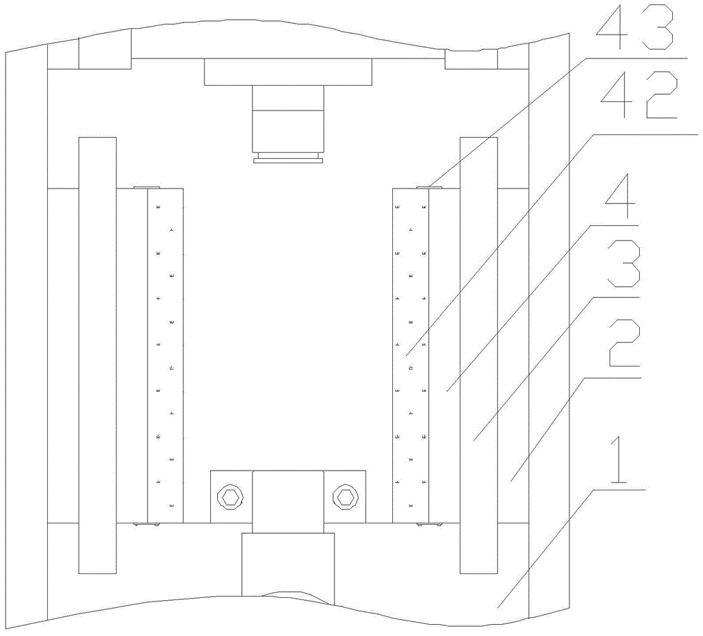
[0013] like figure 1 , figure 2 As shown, a blanking positioning device for a punch is arranged on both sides of the punch frame 1. The main body is composed of two sets of fixing plates 2, two sets of positioning plates 3 and two sets of slide plates 4. The fixing plates 2 are fixed on the punching machine by screws 21. On the frame 1, the fixed plate 2 is provided with a track 22, the positioning plate 3 is provided with a block 31, the positioning plate 3 is slidably arranged on the fixed plate 2, the positioning plate 3 is provided with a card hole 32, and the slide plate 4 is provided with Staple 41, the slide plate 4 is engaged with the clamping hole 32 on the positioning plate 3 through the staple 41, and the slide plate 4 is provided w...


PUM


Abstract

A blanking and positioning device for punching presses, which relates to the technical field of punching press processing and manufacturing, is arranged on both sides of the punching machine frame, and the main body is composed of two sets of fixing plates, two sets of positioning plates and two sets of sliding plates, and the fixing plates are fixed on the punching machine frame by screws On the fixed plate, a track is arranged on the fixed plate, and a block is arranged on the positioning plate. The clamping holes are connected with each other, and a V-shaped groove is arranged on the sliding plate. The beneficial effects of the present invention are: the structure of the present invention is simple, and after the positioning device of the present invention is installed on the punching machine, the position of the stamping part is effectively limited when the stamping part is being stamped, and the stamping failure caused by the position deviation is avoided. Flexible and convenient, easy to popularize and apply.

Description

technical field [0001] The invention relates to the technical field of punch processing and manufacturing, in particular to a punch blanking and positioning device. Background technique [0002] A punch press, in layman's terms, is a stamping press. In national production, the stamping process has the advantages of saving materials and energy, high efficiency, low technical requirements for operators, and the ability to produce products that cannot be achieved by mechanical processing through various mold applications. Its use is more and more extensive. Stamping production is mainly for sheet metal. Through molds, it can make blanking, punching, forming, deep drawing, trimming, fine blanking, shaping, riveting and extrusion parts, etc., which are widely used in various fields. For example, we use switch sockets, cups, cupboards, dishes, computer cases, and even missile aircraft... There are many accessories that can be produced through molds with a punching machine. The d...

Claims


Application Information

Patent Timeline
Patent Type & Authority Patents(China)
IPC IPC(8): B21D43/00B21D37/00
Inventor 张悠斌朱庆国李洋
Owner 绩溪徽腾机械有限公司
Learn More