

Impact resistance test method for aero-engine blade
An aero-engine and test method technology, applied in impact testing, testing material strength using a single impact force, testing of machine/structural components, etc. problems of concentration
Pending Publication Date: 2022-06-17
AECC COMML AIRCRAFT ENGINE CO LTD
View PDF0 Cites 0 Cited by
- Summary
- Abstract
- Description
- Claims
- Application Information
AI Technical Summary
Problems solved by technology
[0004] At present, the most commonly used test method for the impact resistance of composite materials at home and abroad is the target test, which uses a spherical or cylindrical soft body as an impact object to impact the composite material sample at a certain speed and angle, and studies the impact resistance and impact failure mode of the composite material. , but this method usually clamps the test blade horizontally on the specimen holding device. Since the test blade is fixed on the frame by bolts, the test blade can neither adjus
Method used
View moreImage
Smart ImageViewing Examples

Examples
 PUM
 Abstract
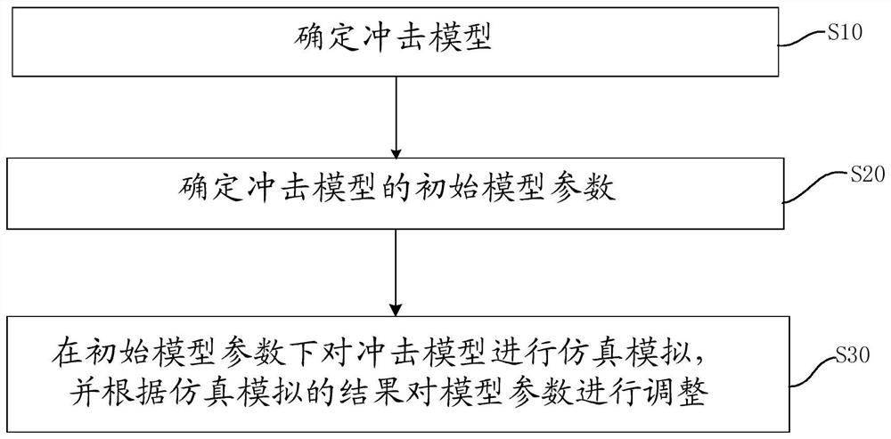
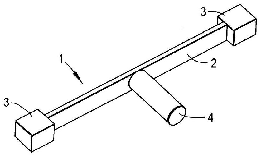
The invention discloses an aero-engine blade impact resistance test method. The aero-engine blade impact resistance test method comprises the following steps that an impact model is determined, the impact model comprises a test blade, an inertia mass block and a soft body, the inertia mass block and the soft body are arranged at the two ends of the test blade respectively, and the inertia mass block is provided with a strip-shaped groove used for clamping the end of the test blade and is freely arranged; initial model parameters of the impact model are determined, wherein the initial model parameters comprise the soft body mass, the soft body length, the soft body diameter, the soft body density, the soft body speed, the test blade size, the mass of an inertial mass block and the constraint width; and carrying out analogue simulation on the impact model under the initial model parameters, and adjusting the model parameters according to an analogue simulation result. The mass blocks fixed at the two ends of the test piece can have rotation freedom degrees in the soft body impact process, and the displacement of the inertial mass blocks at the two ends hardly changes due to inertial confinement in the soft body impact process.
Description
technical field [0001] The invention relates to the technical field of composite material testing, in particular to an impact-resistant testing method of an aeroengine blade. Background technique [0002] Due to the excellent characteristics of composite materials and their obvious advantages such as convenient molding and low cost, composite materials have become an important material for high-performance cold-end components favored by aero-engine design and manufacturing and are widely used in large ducts. On the external casing, rotor blade, stator blade, containment casing, engine nacelle and thrust reverser of turbofan engine and small bypass ratio turbofan engine. [0003] An important index to evaluate the performance of composite material blade is its anti-foreign object impact performance. When an aero-engine is running close to the ground during take-off, landing or low-altitude flight, it is likely to inhale various foreign objects. The inhaled foreign objects wi...
Claims
Login to View More Application Information
Patent Timeline
 IPC IPC(8): G01N3/30G01N3/02G01N3/04G01M7/08
CPCG01N3/30G01N3/02G01N3/04G01M7/08G01N2203/0252G01N2203/0282G01N2203/0452G01N2203/0682
Inventor 张婷李向前
Owner AECC COMML AIRCRAFT ENGINE CO LTD