

Triaxial braid fabric architectures for improved soft body armor ballistic impact performance
a technology of fabric architecture and soft body armor, applied in the direction of textiles and paper, protective equipment, ornamental textile articles, etc., can solve the problems of inefficient development strategy of soft body armor development, increased production cost, and insufficient back face deformation resistan
- Summary
- Abstract
- Description
- Claims
- Application Information
AI Technical Summary
Benefits of technology
Problems solved by technology
Method used
Image

Examples
examples
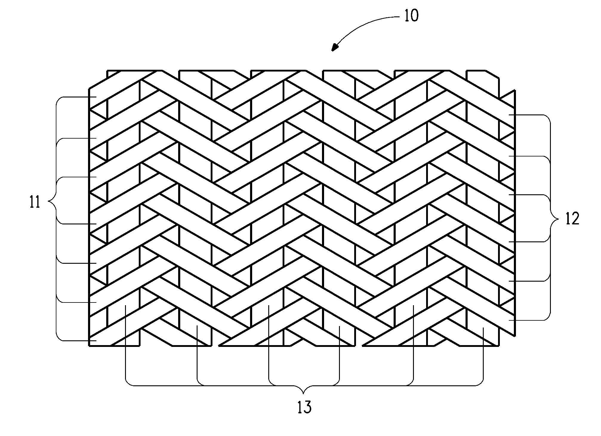
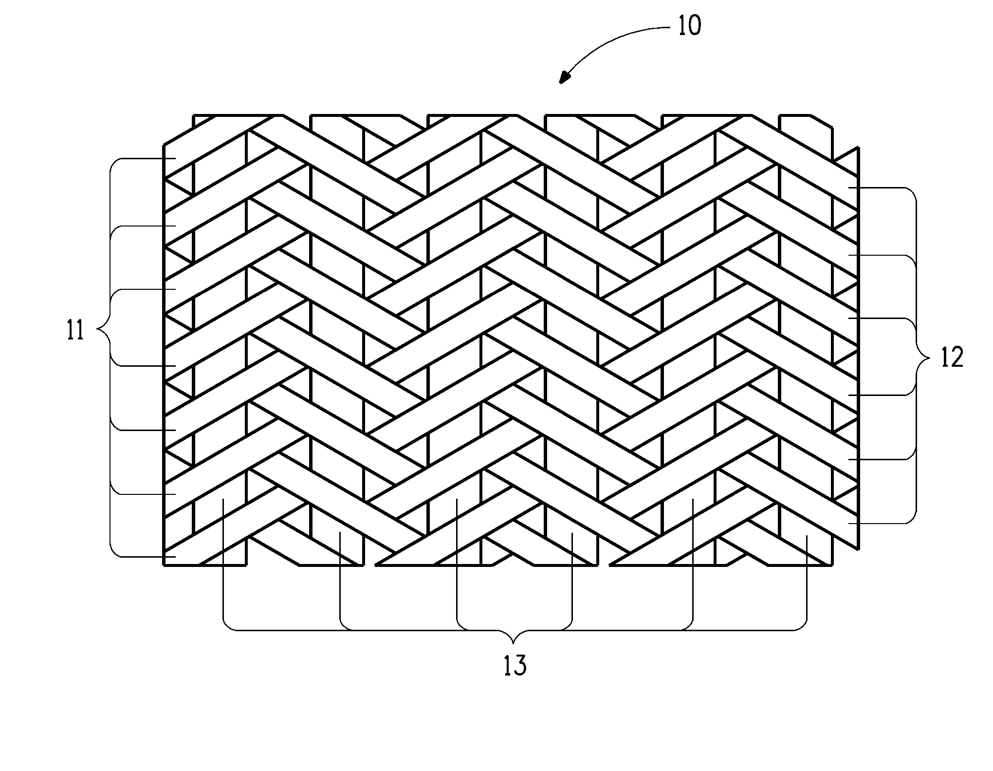
[0067]For the examples and comparative examples presented below, the triaxial braid structures were generated using a tubular braiding process. This braiding operation generated a tubular fabric, with braid yarns oriented in a helical fashion about the tube during the braiding process, and axial yarns oriented parallel to the axis of the tubular braid during its formation. To generate flat fabric for constructing ballistic test panels, the tubular braid was slit along the side, and the resulting flat fabric was cut to the desired size.
[0068]Examples prepared according to the current invention are indicated by numerical values. Control or Comparative Examples are indicated by letters.
example 1
[0073]A 15 in×15 in (38×38 cm) square ballistic test panel was prepared from 22 layers of a braided triaxial fabric generated from a tubular braid produced by A&P Technology, Inc. The yarns used to fabricate the braid were Kevlar® KM2 Plus fiber. The first and second pluralities of yarns (braid yarns) both had a linear density of 666 dtex (600 denier). The third plurality of yarns (axial yarns) had a linear density of 1332 dtex (1200 denier) assembled from two yarns of 666 dtex. The braid construction consisted of a braid angle of 63 degrees and a basis weight of 6.62 oz. / sq.yd (224 gsm). To produce the flat triaxial braid fabric, the 4.85″ diameter tubular braid was slit along one side in the axial direction. From this fabric, 15 in×15 in plies were cut and stacked with all plies oriented in the same direction. The fabric layers were stitched together about the perimeter of the panel ½ in (1.27 cm) from the edge. The areal density of the panel was 4.97 kg / sq.m. (1.01 lbs / sq.ft). Ba...
example 2
[0078]The test panel was fabricated as described in Example 1 using 23 plies of the triaxial braid fabric. The areal density of the panel was 5.17 kg / sq.m. (1.05 lbs / sq.ft). Ballistic resistance performance against 17 grain FSP's was evaluated. The V50 results are shown in Table 2.
[0079]
TABLE 1ArealBackface PerformanceDensityV50VelocityBFSExample(kg / sq · m)(m / s)(m / s)(mm)Comparative5.0246643148Example A43852Comparative4.9949043550Example B43051Comparative4.97459431CompleteExample C42846Comparative5.0245643850Example D437CompleteExample 14.975054383943641
[0080]Complete indicates that there was complete penetration by the bullet.
[0081]
TABLE 2ExampleCompar-Compar-Compar-Compar-ativeativeativeativeExam-Exam-Exam-Exam-Exam-ple Eple Fple Gple Hple 2Areal5.175.175.175.225.17Density(kg / sq · m.)V50610631601608640(m / s)
[0082]Based on the 44 Magnum ballistic testing presented in Table 1 for panels of nearly equivalent areal density, the panel of Example 1 fabricated from triaxial braid fabric ha...
PUM
 Abstract
Description
Claims
Application Information