
Elastomeric balloon support fabric

a technology of elastomeric balloons and fabrics, applied in the direction of ornamental textile articles, catheters, braids, etc., can solve the problems of affecting the quality of balloons, so as to achieve a high degree of stretch and recovery

Inactive Publication Date: 2002-10-31
EI DU PONT DE NEMOURS & CO
View PDF1 Cites 143 Cited by
  • Summary
  • Abstract
  • Description
  • Claims
  • Application Information

AI Technical Summary

Benefits of technology

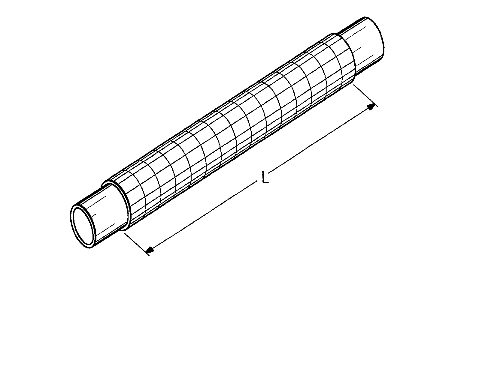
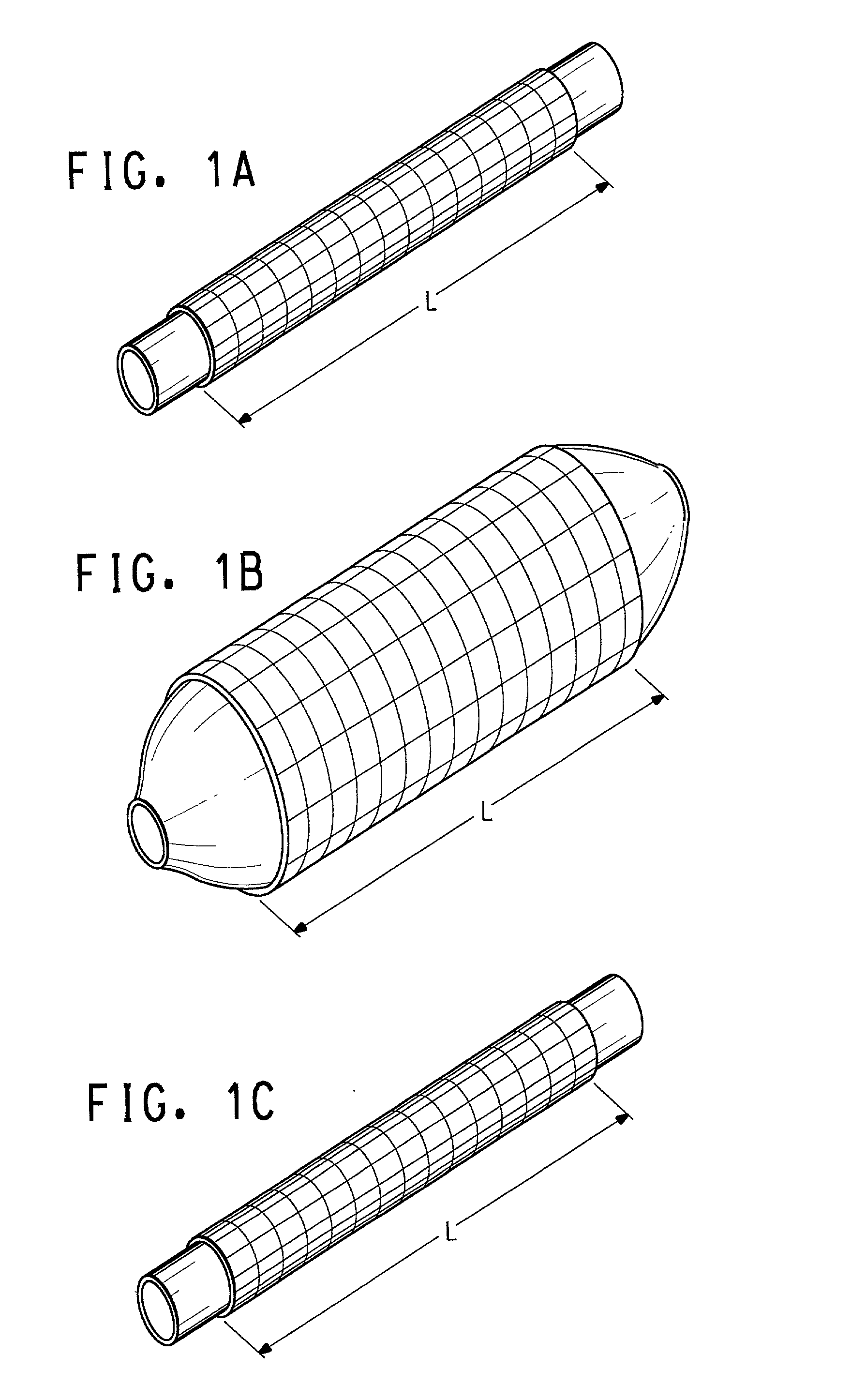
[0018] The balloon covers of the present invention comprise an elastic fabric structure of interconnected yarn, the structure having a high degree of stretch and recovery in the circumferential direction. Preferably, the structure has little if any stretch in the longitudinal direction with the high degree of stretch and recovery in the circumferential direction. The longitudinal yarn preferably is not so elastic as the circumferential yarn and most preferably is a relatively inextensible yarn. By using a relatively inextensible longitudinal yarn and a reversibly-elastic circumferential yarn, the resulting covers are longitudinally stable (i.e. exhibit little or no dimensional change in the longitudinal direction upon expansion and collapsing in the circumferential direction) while being reversibly, and repeatedly expandable and collapsible in the circumferential direction. Preferably, the elastic yarns are selected so that the elastic sleeve (balloon cover) can achieve an expanded dimension of more than two times, even more than 21 / 2 times, the collapsed dimension.

Problems solved by technology

They tend to be self-limiting as to diameter in that they will normally distend up to the rated diameter and not distend appreciably beyond this diameter until rupture due to over-pressurization.
While the inelastic material of the balloon is generally effective in compacting deposits, it tends to collapse unevenly upon deflation, leaving a flattened, wrinkled bag, substantially larger in cross section than the balloon was when it was originally installed.
This enlarged, wrinkled bag may be difficult to remove, especially from small vessels.
Further, because these balloons are made from inelastic materials, their time to complete deflation is inherently slower than elastic balloons.
First, as has been noted, the strongest materials for balloon construction tend to be relatively inelastic. The flattening of catheter balloons made from inelastic materials that occurs upon inflation and subsequent deflation makes extraction and navigation of a deflated catheter somewhat difficult. Contrastingly, highly elastic materials tend to have excellent recovery upon deflation, but are not particularly strong when inflated nor are they self-limiting to a maximum rated diameter regardless of increasing pressure. This severely limits the amount of pressure that can be applied with these devices. It is also somewhat difficult to control the inflated diameter of these devices.
Second, in instances where the catheter is used to deliver some other device into the conduit, it is particularly important that a smooth separation of the device and the catheter occur without interfering with the placement of the device. Neither of the two catheter devices described above is ideal in these instances. A balloon that does not completely compact to its original size is prone to snag the device causing placement problems or even damage to the conduit or balloon. Similarly, the use of a balloon that is constructed of tacky material will likewise cause snagging problems and possible displacement of the device. Latex balloons are generally not used for device placement in that they are considered to have inadequate strength for such use.
Nevertheless, although the "balloon covers" taught in the Campbell et al. patents may have low profile and good trackability, and are able to expand and provide stress support to the balloon, they still leave various needs to be solved.

Method used


Image

  • Elastomeric balloon support fabric
  • Elastomeric balloon support fabric
  • Elastomeric balloon support fabric

Examples


example 1

Braided Elastomeric Fabric Sleeve

[0106] Fabric Description

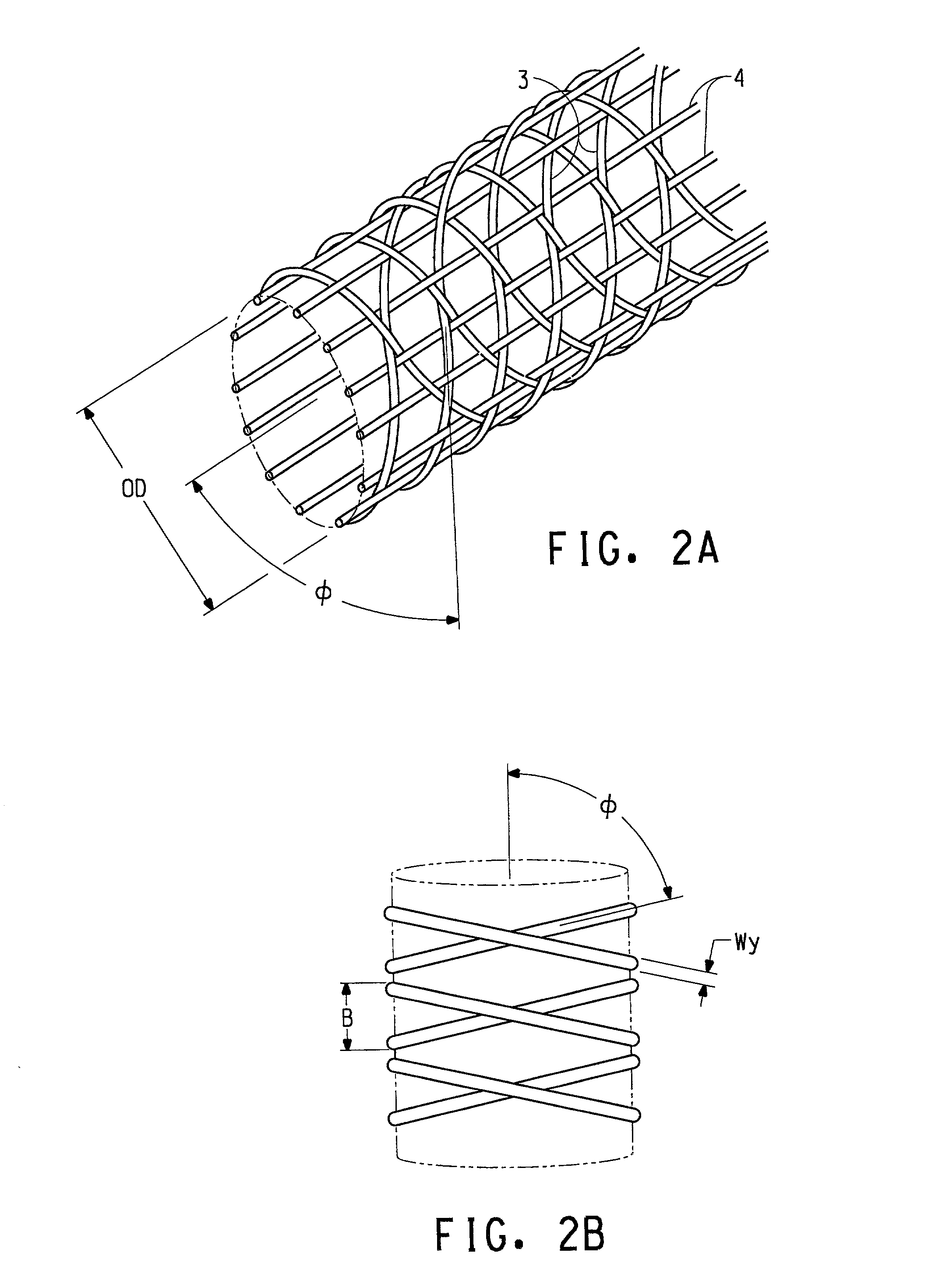
[0107] The yarns in this fabric of this example are interlaced in a tubular braided geometry. Sixteen axial yarns are oriented in the longitudinal direction, and they are interlaced by two braiding yarns. The braiding yarns lie in opposing helices that are nearly perpendicular to the longitudinal axis. There are approximate 254 braiding yarns per inch of tube length. The braid diameter can be varied from about 1 to 4 mm, depending on the internal pressure, with the length of the braid remaining essentially constant.

[0108] Yarn Materials

[0109] The axial yarns are made of polyester yarns (40 denier, 27 filaments). These yarns are generally inextensible with a break elongation of 27%. The braiding yarns, on the other hand, are made of spandex fibers with a break elongation of 600%.

[0110] The spandex yarns (90 denier) have a high degree of recovery from any imposed strain. The spandex yarns permit the braided tube to change diame...

example 2

Woven Elastomeric Fabric Sleeve

[0117] Fabric Description

[0118] The yarns in this fabric are interlaced in a tubular woven geometry. Sixty ends (longitudinal yarns) are oriented in the warp direction and they are interlaced by the perpendicular filling yarn. There are approximately 90 picks (filling yarns) per inch of tube length. The tube diameter varies from about 1.3 to 4.5 mm, depending on the internal pressure, and the length of the tube remains essentially constant.

[0119] Yarn Materials

[0120] The longitudinal ends are made of polyester yarns (40 denier, 27 filaments). These yarns are generally inextensible with a break elongation of 27%. The filling yarn, on the other hand, is made of spandex fibers with a break elongation of 600%.

[0121] The spandex yarns have a high degree of recovery from any imposed strain. The spandex yarns permit the woven tube to change diameter substantially. In the collapsed state the woven diameter is 1.3 mm and this grows to approximately 4.5 mm in th...

example 3

Process for Braiding Elastomeric Fabric Sleeve Directly onto an Inflated Balloon Catheter

[0126] Fabric Description

[0127] The yarns in this fabric are interlaced in a tubular braided geometry. Sixteen axial yarns are oriented in the longitudinal direction and they are interlaced by two braiding yarns. The braiding yarns lie in opposing direction helices that are nearly perpendicular to the longitudinal axis. There are approximate 254 braiding yarns per inch of tube length. The braid diameter varies from about 1 to 4 mm, depending on the internal pressure, and the length of the braid remains essentially constant.

[0128] Yarn Materials

[0129] The axial yarns are made of polyester fibers (40 denier, 27 filaments). These yarns are generally inextensible with a break elongation of 27%. The braiding yarns, on the other hand, are made of spandex fibers with a break elongation of 600%.

[0130] The spandex yarns have a high degree of recovery from any imposed strain. The spandex yarns permit the ...


PUM

PropertyMeasurementUnit
Angleaaaaaaaaaa
Angleaaaaaaaaaa
Angleaaaaaaaaaa

Abstract

Balloon catheter covers are elastic fabric structures of interconnected yarns, the structure having a high degree of stretch and recovery in the circumferential direction with little change in dimension in the longitudinal direction during multiple pressurization cycles over full range of inflation and deflation of the balloon catheter. The covers have longitudinal yarns positioned at about zero degrees to the balloon axis and reversibly-stretchable, circumferential yarns positioned at a high angle Ø to the axis. A method for making the balloon catheter covers allowing nearly orthogonal placement of circumferential and longitudinal yarns involves triaxial braiding a minimum number of elastomeric braid yarns with multiple axial yarns to provide maximum convergence angle (approaching 90 degrees).

Description

[0001] This application claims the benefit of U.S. Provisional Application No. 60 / 271,770, filed Feb. 27, 2001.BACKGROUND OF INVENTION[0002] 1. Field of Invention[0003] The present invention relates to balloon catheters used in a variety of surgical procedures and particularly to elastomeric balloon support fabrics used to form elastomeric sleeves or balloon covers for use with balloon catheters. It also relates to a process for making such fabrics.[0004] 2. Background Discussion and Related Art[0005] Balloon catheters of various forms are commonly employed in a number of surgical procedures. These devices comprise a thin catheter tube that can be guided through a body conduit of a patient such as a blood vessel and a distensible balloon located at the distal end of the catheter tube. Actuation of the balloon is accomplished through use of a fluid filled syringe or similar device that can inflate the balloon by filling it with fluid (e.g., water or saline solution) to a desired degr...

Claims


Application Information

Patent Timeline
IPC IPC(8): A61F2/958A61L29/08A61L29/12A61M25/00A61M25/10D04C1/06
CPCA61L29/085A61L29/12A61M25/10A61M25/1027Y10T428/139A61M2025/1075A61M2025/1084D04C1/06A61M2025/1031D04C3/48D10B2401/061D10B2403/02411D10B2509/06
Inventor SAMUELS, SAM L.POPPER, PETERDIMAIO, WILLIAM G.
Owner EI DU PONT DE NEMOURS & CO
Learn More