
Grease-Free Buffer Optical Fiber Buffer Tube Construction Utilizing a Water-Swellable, Texturized Yarn

a technology of texturized yarn and buffer tube, which is applied in the direction of optical light guides, fibre mechanical structures, instruments, etc., can solve the problems of damage to the performance of optical fibers and too much bulk inside the tubes, and achieve the effect of reducing length

Active Publication Date: 2008-11-27
DRAKA COMTEQ BV
View PDF12 Cites 142 Cited by
  • Summary
  • Abstract
  • Description
  • Claims
  • Application Information

AI Technical Summary

Benefits of technology

[0003]The invention comprises a buffered optical fiber arrangement that includes a buffer tube in which is provided optical fibers and a texturized yarn coated with a water-swellable material. The filament diameter of the yarn used in the present invention may be between about 5 microns and about 100 microns, more preferably between about 10 and about 60 microns, still more preferably between about 20 and about 40 microns. The linear density, or denier expressed in grams per 9000 meters, of the base yarn may be between about 100 and 1000, more preferably between about 200 and 600, or still more preferably between about 250 and 350. The degree of decrease in length (the “degree of texturizing”) between the perfectly straight filaments before texturizing and the texturized filament may be between 1 percent and 90 percent, more preferably between about 2 percent and 50 percent, or still more preferably between about 5 percent and 25 percent.

Problems solved by technology

However, due to their irregular geometry and granularity , the particles of powder on the carrier yarn in the first instance can damage the performance of the optical fibers.
Also, with respect to the water-swellable filaments spun with polyester yarns, too much bulk must be added inside the tubes.

Method used


Image

  • Grease-Free Buffer Optical Fiber Buffer Tube Construction Utilizing a Water-Swellable, Texturized Yarn
  • Grease-Free Buffer Optical Fiber Buffer Tube Construction Utilizing a Water-Swellable, Texturized Yarn
  • Grease-Free Buffer Optical Fiber Buffer Tube Construction Utilizing a Water-Swellable, Texturized Yarn

Examples


Embodiment Construction

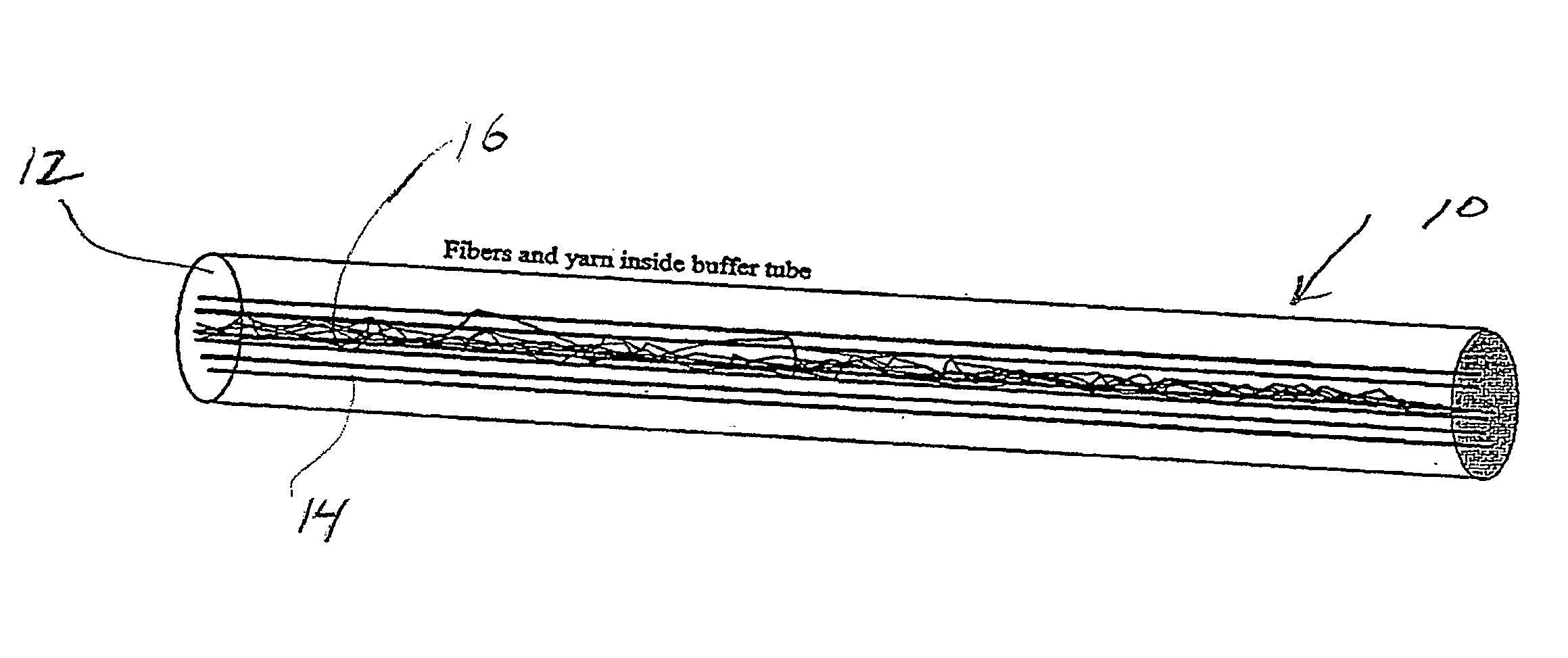
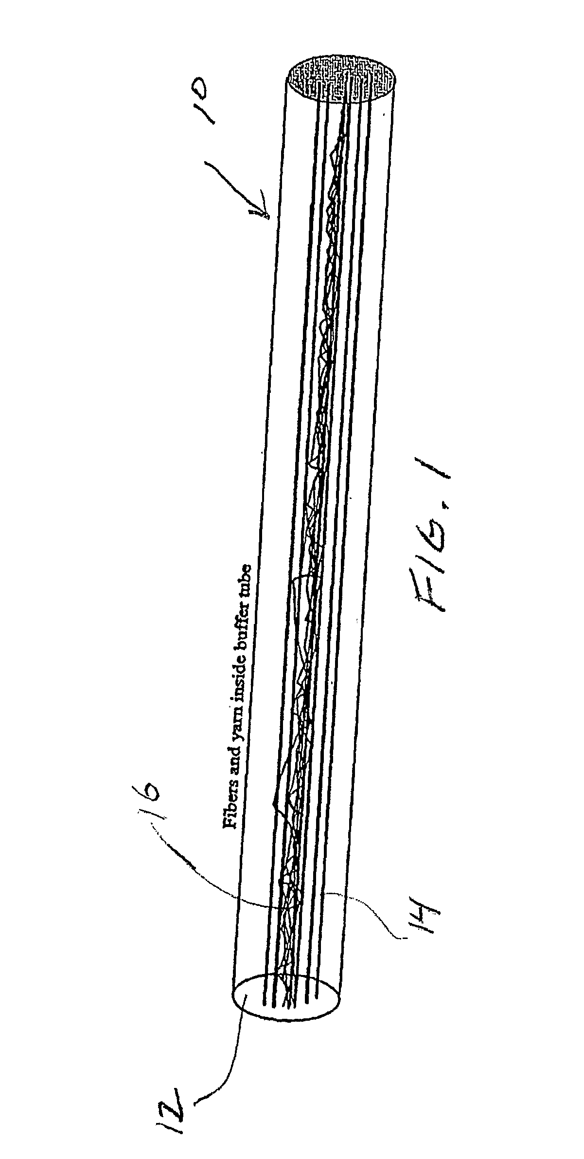
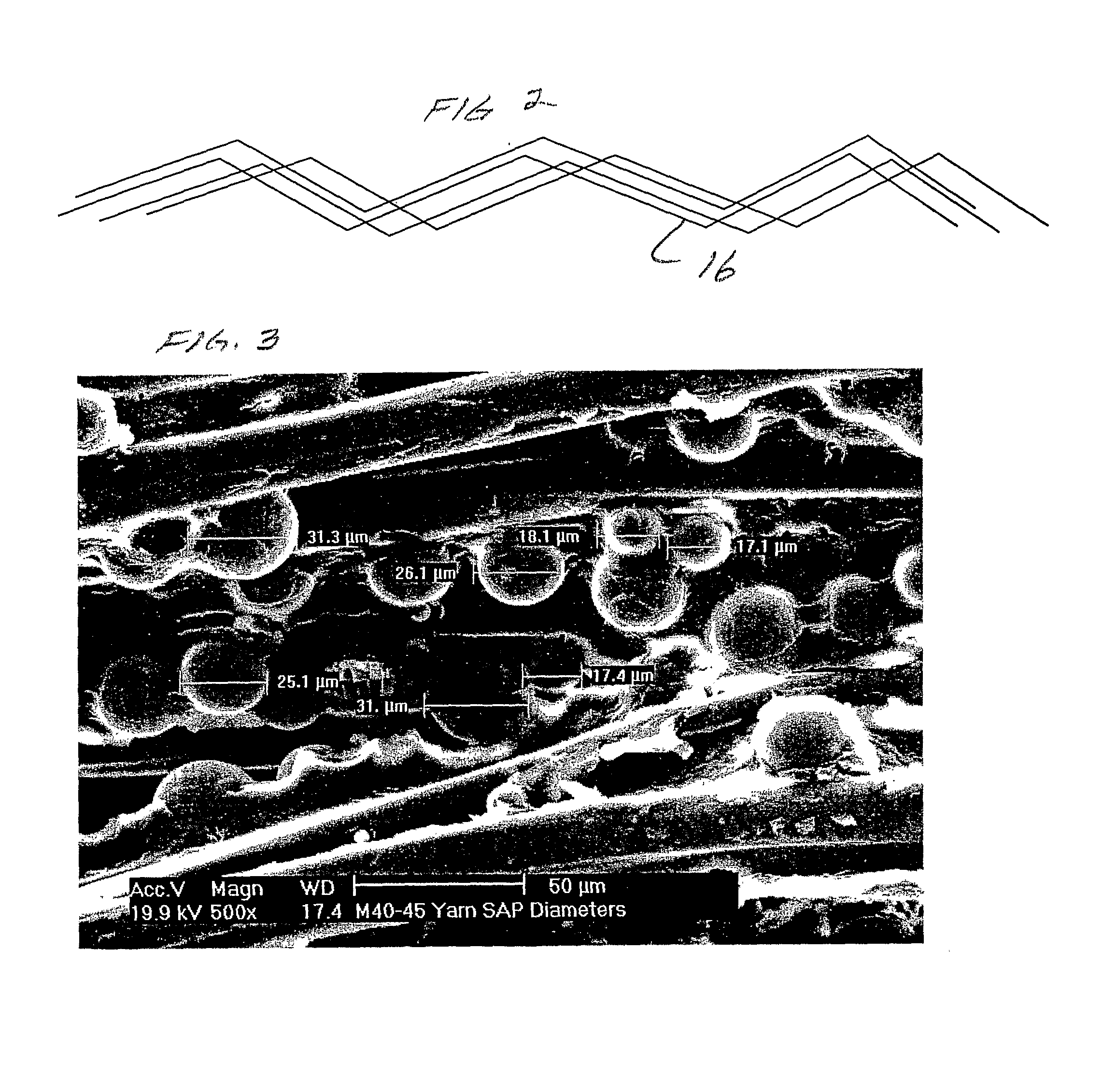
[0008]With reference to FIG. 1, the buffered optical fiber arrangement 10 according to an embodiment of the present invention includes a buffer tube 12 containing optical fibers 14 and an improved yarn 16 according to the present invention. The yarn 16 comprises a texturized filament structure using, for example, polyester filaments coated with water-swellable material, such as polyacrylate from a methanol or other solvent solution, after which the solvent is driven off. The solvent coating system provides very small, very smooth and generally spherical domains of polyacrylate on the carrier yarn that do not apply point stresses to the optical fibers, while integrating the water-swellable component with the carrier yarn. According to the invention, the yarn is texturized so that when the yarn is not under tension it assumes a fluffy configuration, further easing the stresses on the optical fibers. An example of a low-denier, texturized yarn product for use in the present invention i...


PUM


Abstract

A buffered optical fiber arrangement that includes a buffer tube in which is provided optical fibers and a texturized yarn coated with a water-swellable material. The filament diameter of the yarn used in the present invention may be between about 5 microns and about 100 microns, more preferably between about 10 and about 60 microns, still more preferably between about 20 and about 40 microns. The linear density, or denier in grams per 9000 meters, of the base yarn may be between about 100 and 1000, more preferably between about 200 and 600, or still more preferably between about 250 and 350. The degree of decrease in length (the "degree of texturizing") between the perfectly straight filaments before texturizing and the texturized filament may be between 1 percent and 90 percent, more preferably between about 2 percent and 50 percent, or still more preferably between about 5 percent and 25 percent.

Description

CROSS-REFERENCE TO RELATED APPLICATIONS[0001]This Application claims the benefit of U.S. Provisional Application No. 60 / 700,751, filed in the United States Patent and Trademark Office on Jul. 20, 2005. That application is hereby incorporated herein by reference in its entirety.BACKGROUND OF THE INVENTION[0002]Optical fiber cables typically include optical fibers or ribbons provided in buffer tubes. For water blocking purposes, the buffer tube includes either a filling gel or a water-swellable material, such as a water-swellable yarn. Water-swellable yarns typically comprise granular powder glued to a polyester carrier yarn or polyacrylate filaments that are bundled onto polyester carrier yarns. However, due to their irregular geometry and granularity , the particles of powder on the carrier yarn in the first instance can damage the performance of the optical fibers. Also, with respect to the water-swellable filaments spun with polyester yarns, too much bulk must be added inside the ...

Claims


Application Information

Patent Timeline
IPC IPC(8): G02B6/00
CPCG02B6/4429G02B6/4494
Inventor OVERTON, BOBCHEATLE, WAYNE
Owner DRAKA COMTEQ BV
Learn More