
Wind-resistant column structure of large-span maintenance hangar

A wind-resistant column and large-span technology, applied in wind power generation, building structure, building type, etc., can solve problems affecting node stress, design force deviation, node application, etc.

Active Publication Date: 2022-07-08
CHINA AVIATION PLANNING & DESIGN INST GRP
View PDF7 Cites 0 Cited by
  • Summary
  • Abstract
  • Description
  • Claims
  • Application Information

AI Technical Summary

Problems solved by technology

[0003] However, this solution has the following problems: When the hangar is subjected to a large external wind force and the wind-resistant column needs to play a role, it will first pull the node to deform slightly, and then the steel plate can exert force on the node to achieve the wind-resistant effect
Secondly, the wind-resistant column structure will exert a vertical force on the node when the actual height of the node deviates from the design height, affecting the actual force of the node, resulting in a deviation from the design force

Method used


Image

  • Wind-resistant column structure of large-span maintenance hangar
  • Wind-resistant column structure of large-span maintenance hangar
  • Wind-resistant column structure of large-span maintenance hangar

Examples


Embodiment 1

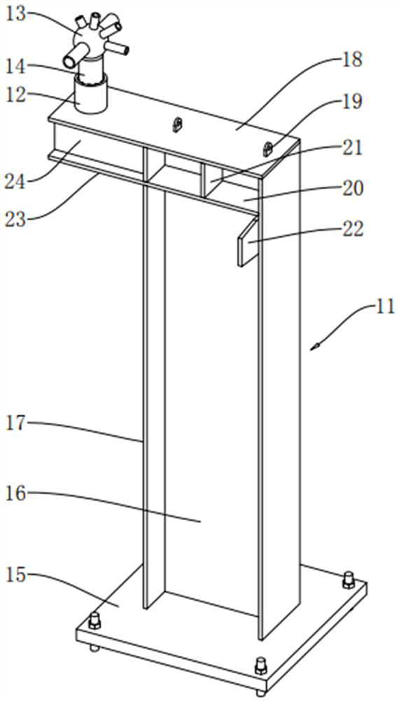
[0038] like figure 2 As shown, the wind-resistant column structure of the large-span maintenance hangar includes a column body 11, an outer support tube 12 connected above the column body 11, and an inner support tube 14 connected below the node 13. The inner support tube 14 is inserted into the outer support tube 12. Inside.

[0039] like figure 2 As shown, the column 11 includes a bottom plate 15, a neutral plate 16 vertically fixed above the bottom plate 15, and two side vertical plates 17 vertically fixed above the bottom plate 15. The neutral plate 16 is welded and fixed and the side vertical plates 17 are perpendicular to the neutral plate 16 . The upper end of the neutral plate 16 is provided with an upper horizontal plate 18 parallel to the bottom plate 15 . Two lifting lugs 19 with holes are welded and fixed on the upper horizontal plate 18 . A lower horizontal plate 20 is welded and fixed on both sides of the neutral plate 16 at a position below the upper horiz...

Embodiment 2

[0044] like Figure 4 As shown, the wind-resistant column structure of the large-span maintenance hangar includes a column body 11, an outer support tube 12 connected above the column body 11, and an inner support tube 14 connected below the node 13. The inner support tube 14 is inserted into the outer support tube 12. Inside.

[0045] like Figure 4 As shown, the column body 11 includes a bottom plate 15, a neutral plate 16 vertically fixed above the bottom plate 15, and two side vertical plates 17 vertically fixed above the bottom plate 15. The neutral plate 16 is welded and fixed and the side vertical plates 17 are perpendicular to the neutral plate 16 . The upper end of the neutral plate 16 is provided with an upper horizontal plate 18 parallel to the bottom plate 15 , and the upper horizontal plate 18 is welded and fixed to the neutral plate 16 and the two side vertical plates 17 . Two lifting lugs 19 with holes are welded and fixed on the upper horizontal plate 18 . ...

Embodiment 3

[0048] like Image 6 As shown, the wind-resistant column structure of the large-span maintenance hangar includes a column body 11, an outer support tube 12 connected above the column body 11, and an inner support tube 14 connected below the node 13. The inner support tube 14 is inserted into the outer support tube 12. Inside.

[0049] like Image 6 As shown, the column body 11 includes a bottom plate 15, a neutral plate 16 vertically fixed above the bottom plate 15, and two side vertical plates 17 vertically fixed above the bottom plate 15. The neutral plate 16 is welded and fixed and the side vertical plates 17 are perpendicular to the neutral plate 16 . The upper end of the neutral plate 16 is provided with an upper horizontal plate 18 parallel to the bottom plate 15 . Two lifting lugs 19 with holes are welded and fixed on the upper horizontal plate 18 . A lower horizontal plate 20 is welded and fixed to a position below the upper horizontal plate 18 on both sides of the...


PUM


Abstract

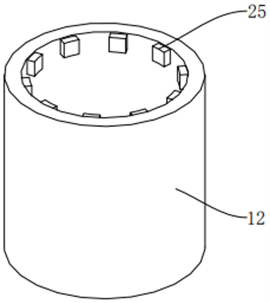
The invention relates to the field of wind-resistant columns, in particular to a wind-resistant column structure of a large-span maintenance hangar. A wind-resistant column structure of a large-span maintenance hangar comprises a column body, an outer supporting pipe connected to the upper portion of the column body and an inner supporting pipe connected to the lower portion of a joint, the inner supporting pipe is inserted into the outer supporting pipe, at least three supporting pieces are evenly distributed on the inner side wall of the outer supporting pipe in the circumferential direction, and the supporting pieces abut against the outer wall of the inner supporting pipe. The supporting piece in the outer supporting pipe is matched with the inner supporting pipe in an abutting mode, so that when the wind-resistant column plays a wind-resistant role, due to the fact that the supporting block is tightly matched with the inner supporting pipe, acting force can be directly conducted to the column body, and the wind-resistant effect is played in time. And meanwhile, no rigid connection structure exists between the inner supporting pipe and the outer supporting pipe, so that longitudinal acting force cannot be applied to the joint, and the stress of the joint is closer to design.

Description

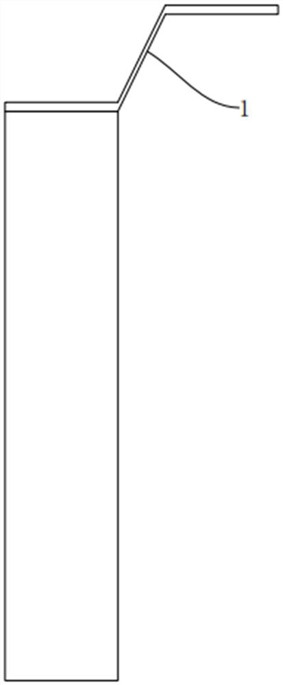
technical field [0001] The present application relates to the field of wind-resistant columns, in particular to a wind-resistant column structure for a large-span maintenance hangar. Background technique [0002] There are many nodes in the structural design of the long-span maintenance hangar. Considering the wind resistance stability of the hangar, wind resistance columns are usually set at the positions of some nodes. Existing wind columns such as figure 1 As shown, a steel plate is arranged above the column body of the existing wind resistance column to connect the column body and the node to play a wind resistance effect. [0003] However, this scheme has the following problems: when the hangar is subjected to a large external wind force and the anti-wind column needs to function, the node will be pulled to a small degree of deformation first, and then the steel plate can exert force on the node to play a wind-resistant effect. Secondly, when the actual height of the ...

Claims


Application Information

Patent Timeline
Patent Type & Authority Applications(China)
IPC IPC(8): E04H5/06E04H9/14E04B1/58E04B1/92
CPCE04H5/06E04H9/14E04B1/58E04B1/92Y02E10/728
Inventor 沈顺高金来建朱丹汤红军赵伯友
Owner CHINA AVIATION PLANNING & DESIGN INST GRP
Learn More