
Omnibearing correction module

A calibration module and all-round technology, applied in the direction of electrical components, conveyor objects, transportation and packaging, etc., can solve problems such as chip collision, intermediary platform is difficult to move quickly, and the transmission module is large in size and is not suitable for fast movement, etc., to achieve safe swing positive chip effect

Pending Publication Date: 2022-07-19
AELONG IND CO LTD
View PDF0 Cites 0 Cited by
  • Summary
  • Abstract
  • Description
  • Claims
  • Application Information

AI Technical Summary

Problems solved by technology

However, when the existing method moves the chip and puts it into the tray or performs follow-up operations, because the chip cannot be perfectly picked up at the predetermined position and angle of the system every time, the transmission module must be fine-tuned for the position and angle to be smooth. Let the chip be placed in the next process, or use an additional adjustment module to move the chip that has been sucked up, or the transmission module to place the chip on an intermediary platform first, and the intermediary platform first moves and rotates the angle of the chip, The transmission module performs another suction to facilitate subsequent actions; but these three methods have their own disadvantages, for example: the transmission module itself is large and not suitable for fast movement, so it takes time to align; some chips are thin and brittle, It is not suitable to be clamped by the adjustment module; one more transport to the intermediary platform will result in one more risk of chip collision, and the intermediary platform is also difficult to move quickly

Method used


Image

  • Omnibearing correction module
  • Omnibearing correction module
  • Omnibearing correction module

Examples


Embodiment Construction

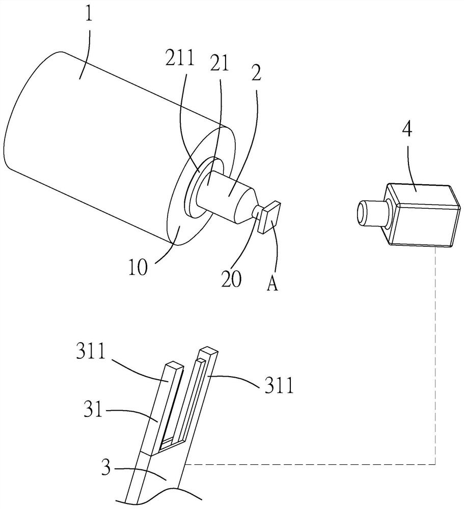
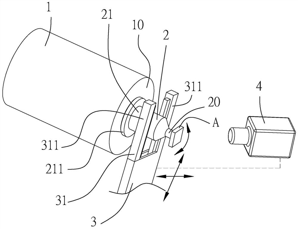
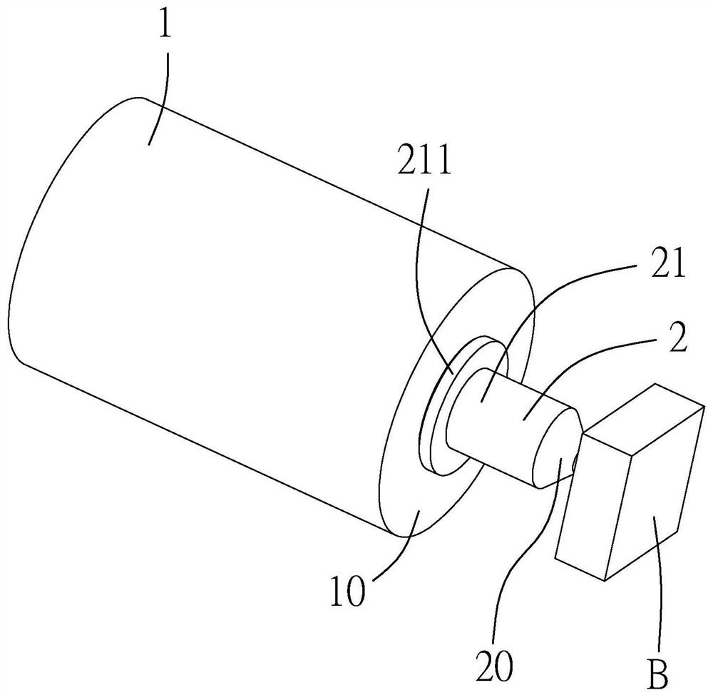
[0039] see Figure 1 to Figure 4 , discloses the drawings of the embodiments of the present invention, the embodiment (1) of the omnidirectional correction module of the present invention includes a transmission unit 1, which has an installation plane 10, the transmission unit 1 has a degree of freedom to move in space, and the transmission unit 1 can be a robotic arm; a suction nozzle unit 2, which has a suction end 20 and an oppositely arranged mounting end 21, the suction end 20 can absorb a chip A or other objects to be suctioned, and the mounting end 21 is detachably installed on the The installation plane 10 of the transmission unit 1, in this embodiment (1), the installation end 21 of the suction nozzle unit 2 extends along the extension direction of the installation plane 10 with a mounting flange 211;

[0040] An adjustment unit 3, which has an adjustment end 31 corresponding to the shape of the suction nozzle unit 2 and a control element (not shown). The adjustment e...


PUM


Abstract

An omnibearing correction module comprises a transmission unit which is provided with a mounting plane and has a degree of freedom of moving in space; the suction nozzle unit is provided with an adsorption end and a mounting end which is oppositely arranged, the adsorption end can adsorb a chip or other articles to be adsorbed, and the mounting end is detachably mounted on the mounting plane of the transmission unit; the adjusting unit is provided with an adjusting end corresponding to the shape of the suction nozzle unit and a control element, and the adjusting end enables the suction nozzle unit to move and rotate on the mounting plane; and the visual identification unit is electrically connected with the control element of the adjusting unit. After the visual identification unit is used for identifying the difference between the chip and the position required by the system, the adjusting unit is used for moving the suction nozzle unit for alignment, and compared with an existing device and method, the chip straightening device has the effect of quickly and safely straightening the chip.

Description

technical field [0001] The invention relates to a chip moving device, in particular to an omnidirectional correction module that can quickly and safely straighten the chip. Background technique [0002] Chips have become an indispensable part of life in the modern age with advanced technology, but chips must undergo many moves between devices during processing, so there are many devices that move chips. However, in the existing method, when the chip is moved and placed in the tray or for subsequent operations, the chip cannot be perfectly absorbed in the predetermined position and angle of the system every time, and the transmission module must be fine-tuned for the position and angle to be smooth. Let the chip align and proceed to the next process, or use an additional adjustment module to move the chip that has been sucked up, or the transmission module first places the chip on an intermediate platform, and the intermediate platform first moves and rotates the angle of the...

Claims


Application Information

Patent Timeline
IPC IPC(8): H01L21/677H01L21/683
CPCH01L21/6838H01L21/67742
Inventor 林博浩李建申
Owner AELONG IND CO LTD
Learn More