Grid-connected converter model prediction control method and control system

A model predictive control and converter technology, applied in the direction of converting AC power input to DC power output, single-grid parallel feeding arrangement, output power conversion device, etc. The effect of dynamic properties

Pending Publication Date: 2022-07-22
深圳市慧能互联科技有限公司
View PDF0 Cites 0 Cited by
  • Summary
  • Abstract
  • Description
  • Claims
  • Application Information

AI Technical Summary

Problems solved by technology

[0005] In view of this, the purpose of the present invention is to provide a model predictive control method and control system for grid-connected converters, aiming at solving the technical problems that the existing model prediction affects the dynamic characteristics of the consideration model and avoiding the use of high-order equations

Method used


Image

  • Grid-connected converter model prediction control method and control system
  • Grid-connected converter model prediction control method and control system
  • Grid-connected converter model prediction control method and control system

Examples


Embodiment 1

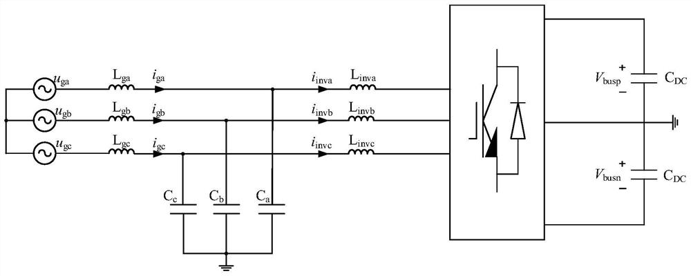
[0088] The present invention provides a model predictive control method for a grid-connected converter, which is applied in a grid-connected converter model predictive control system. Please refer to figure 1 , which is the topology circuit diagram of the grid-connected converter, the LCL filter is used as the filter interface with the grid, L ga , L gb ,L gc It is the three-phase filter inductance on the grid side, and the inductance value is the same as L g , C a , C b , C c It is a three-phase AC filter capacitor, and the capacitance values ​​are the same as C, L inva , L invb ,L invc It is the filter inductance of the converter side, and the inductance value is the same as L inv , C DC It is the DC bus filter capacitor. u ga , u gb , u gc are the sampled voltages of the ABC phase of the power grid, respectively, and the voltage reference points are figure 1 in the land. Due to the symmetry of the topology, the method described in the embodiments of the prese...

Embodiment 2

[0168] The present application also provides a grid-connected converter model predictive control system, which uses the grid-connected converter model predictive control method to realize predictive control of the grid-connected converter. see Figure 5 and Image 6 , the grid-connected converter model predictive control system includes an interconnected definition module 10, a cost function establishment module 20, an acquisition module 30, a calculation module 40 and a control output module 50;

[0169] The defining module 10 is configured to define the switching control period of the converter;

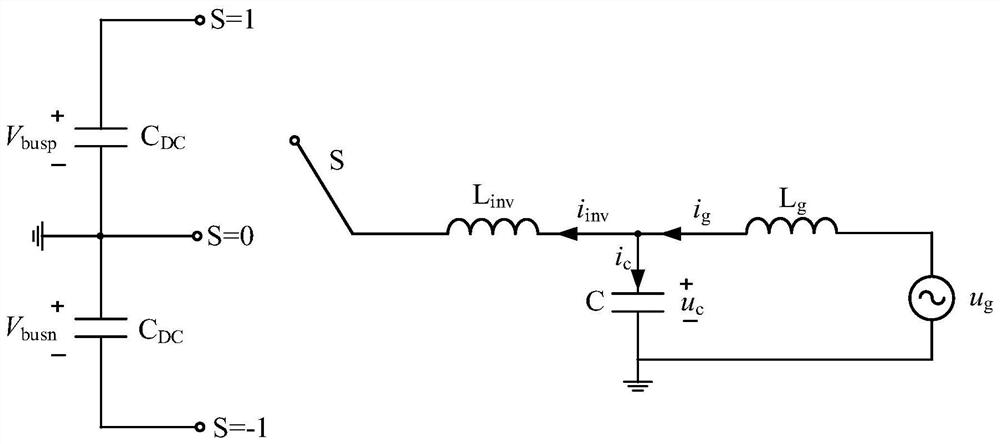
[0170] Specifically, defining the switching control period of the converter includes: defining S as the switching state, S=1, and the voltage on the side of the converter is V busp ; S=0, the voltage on the converter side is 0; S=-1, the voltage on the converter side is -V busn ; Define the on-action interval of adjacent switches as the rising period, the adjacent switch-off act...


PUM


Abstract

The invention provides a grid-connected converter model prediction control method and system, and belongs to the technical field of power electronics. According to the method, the voltage of the converter side is determined according to a defined switching period, and a cost function for controlling switching of a switching device of the converter is established; and obtaining an optimal problem expression of the next switching control period when the cost function is minimum according to the obtained circuit parameter value of the output end of the converter in the current switching control period, and obtaining the switching state of a switching tube of the converter in the next switching control period according to the optimal problem expression. And generating a trigger signal according to the switching state to control on-off of a switching device of the converter. According to the embodiment of the invention, on the premise of a first order, the control function keeps the dynamic characteristics of the LCL grid-connected converter model and completes model-based prediction control, the dynamic characteristics of the system are increased, and optimization of multiple targets can be realized.

Description

technical field [0001] The invention relates to the technical field of power electronics, in particular to a model predictive control method and control system of a grid-connected converter. Background technique [0002] Generally speaking, the output end of the grid-connected converter is equipped with a filter device to suppress the output harmonics of the converter. LCL filters are widely used in grid-connected converters because of their advantages of small size and high-frequency harmonic attenuation. In the related products of the flow device. [0003] Traditionally, methods such as proportional integral (PI), proportional resonance (PR) and repetitive control are generally used to control grid-connected converters. However, these methods are difficult to achieve multi-objective optimization. Model predictive control has the advantages of good dynamic performance and multi-objective optimization, which can provide a good support for the performance improvement and opt...

Claims


Application Information

Patent Timeline
Patent Type & Authority Applications(China)
IPC IPC(8): H02M7/537H02M1/12H02J3/38
CPCH02M7/537H02M1/126H02J3/381
Inventor 肖英龚钢
Owner 深圳市慧能互联科技有限公司
Why Eureka
Try Eureka