Intelligent dismounting equipment for insert injection molding terminal

An insert injection molding and terminal technology, which is applied in the direction of household components, household appliances, and other household appliances, can solve the problems of damage to the terminal body, difficulty in separating the injection mold from the terminal body, etc., and achieve the effect of saving power

Pending Publication Date: 2022-07-29
安徽思科赛德电子科技有限公司
View PDF7 Cites 0 Cited by
  • Summary
  • Abstract
  • Description
  • Claims
  • Application Information

AI Technical Summary

Problems solved by technology

[0005] The purpose of the present invention is to knock the lower surface of the injection molded terminal housing through the telescopic plate in the shrink box, and the generated vibration promotes the separation of the injection molded terminal housing and the terminal body, and the data acquisition unit and data processing unit installed inside the connection box And the data execution unit, so that the separation frame can accurately separate the injection molded terminal shell and the terminal body at the corresponding position, solve the problem that the injection mold and the terminal body are difficult to separate, and manual operation is easy to cause damage to the terminal body. Intelligent disassembly equipment for injection molded terminals

Method used


Image

  • Intelligent dismounting equipment for insert injection molding terminal
  • Intelligent dismounting equipment for insert injection molding terminal
  • Intelligent dismounting equipment for insert injection molding terminal

Examples


Embodiment 1

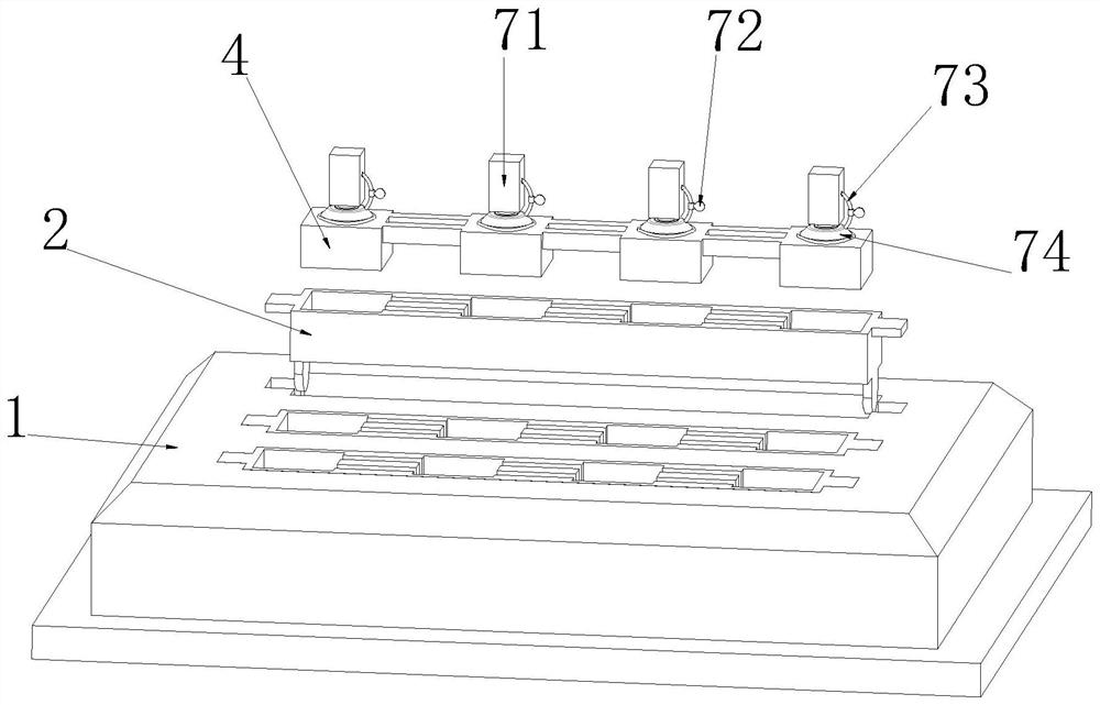
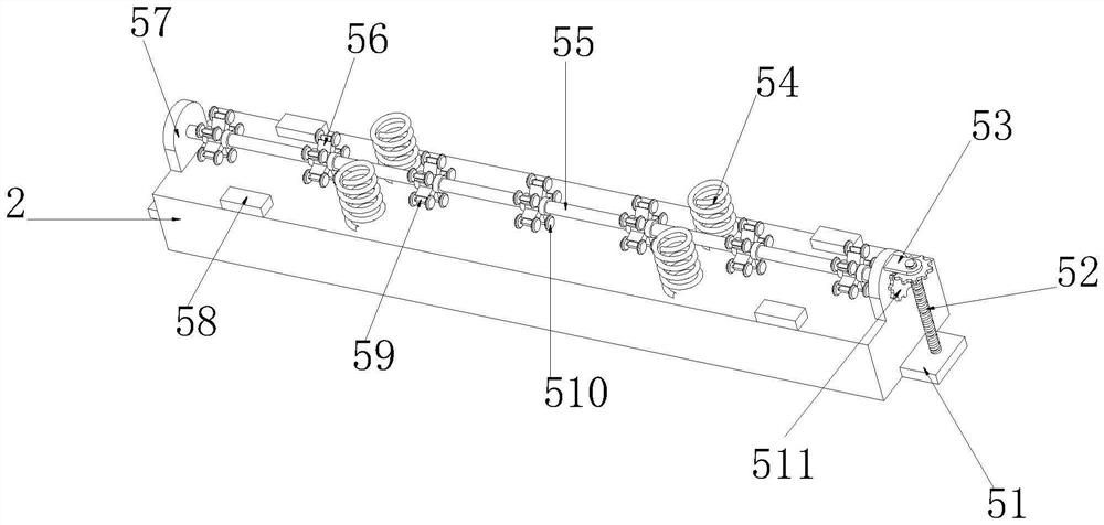
[0035] see Figure 3-4As shown in the figure, an intelligent disassembly device for inserting injection-molded terminals includes an injection mold 1, an injection-molded terminal shell 2, a terminal groove 3 and a terminal body 4. The injection-molded terminal shell 2 is connected to the upper surface of the injection-molded terminal shell 2. There are four terminal slots 3 on the surface, and the terminal body 4 is arranged inside the terminal slot 3. The lower surface of the injection-molded terminal shell 2 is integrally formed with a connecting plate 57 on both sides. The outer side wall of the knocking shaft 55 is connected with a number of evenly distributed telescopic boxes 56 through the connecting ring. The other end is connected to the inner upper surface of the telescopic box 56 through the extension spring, the extension plate 59 drives the extension spring to shrink and stretch during the movement of the position, and the inner lower surface of the injection term...

Embodiment 2

[0039] see Figure 5-6 As shown, a movable cavity 63 is opened on the side of the inner side wall of the injection-molded terminal shell 2 close to the terminal slot 3, and a sliding groove 61 is opened on both sides of the inner side of the injection-molded terminal shell 2 close to the movable cavity 63, and the inner side wall of the injection-molded terminal shell 2 corresponds to the sliding groove 61. A movable baffle 65 is slidably connected at the position, an electric push rod 64 is connected on both sides of the inner lower surface of the movable cavity 63, one end of the electric push rod 64 is connected with a separation frame 62, and the other end is directly connected to the bottom surface of the movable cavity 63, The inner side wall of the injection-molded terminal shell 2 is provided with a side sliding cavity at the position corresponding to the movable baffle 65, and the inner lower surface of the injection-molded terminal shell 2 is provided with a bottom sl...

Embodiment 3

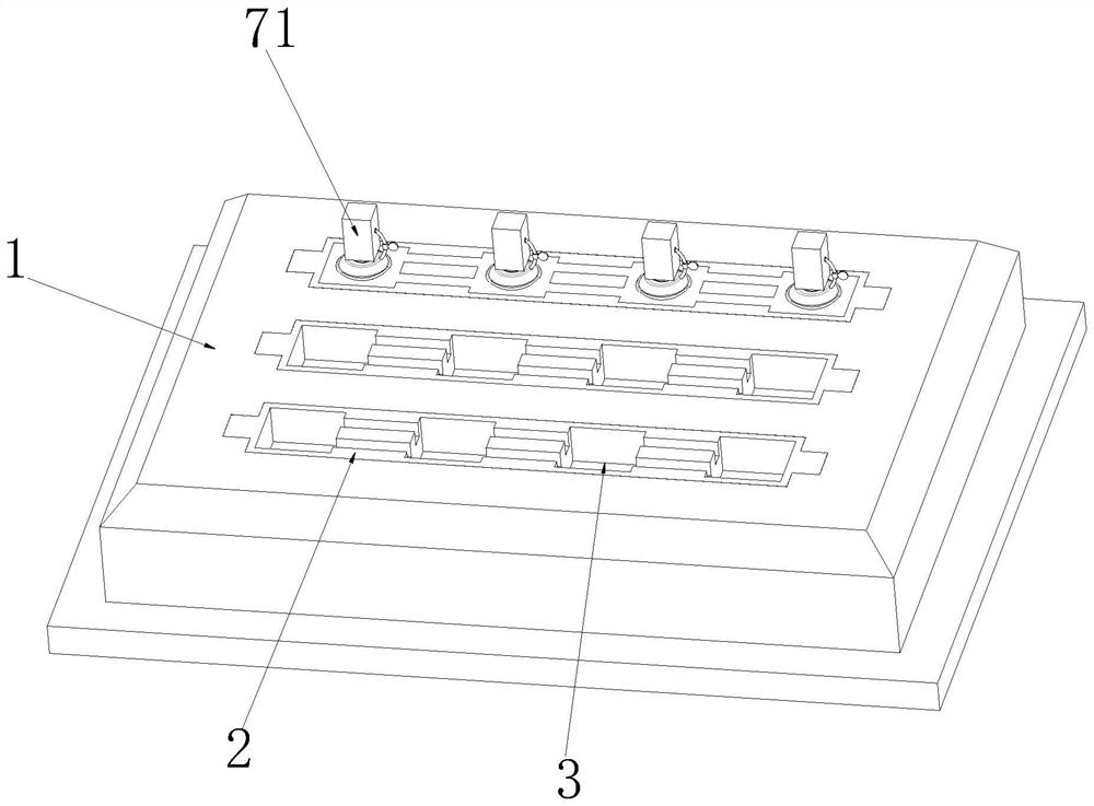
[0042] see Figure 1-2 As shown, the upper surface of the injection mold 1 is provided with a connection box 71 above the injection terminal shell 2, and a suction pump is connected inside the connection box 71 at the position corresponding to the suction cup 74, and the suction pump is connected with the suction cup 74 through the air duct 73. The lower end of the connection box 71 is connected with a suction cup 74, the outer side wall of the connection box 71 is connected with an air duct 73, the outer side wall of the air duct 73 is connected with a barometer 72, the upper end of the connection box 71 is connected with a tension telescopic rod through a traction rope, and the outer side wall of the traction rope is connected with a tension sensor The side of the upper surface of the injection-molded terminal shell 2 close to the terminal slot 3 is connected with an infrared distance sensor;

[0043] The air pressure data inside the suction cup 74 detected by the air pressu...


PUM


Abstract

The invention relates to an insert injection molding terminal dismounting technology, aims to solve the problems that an injection mold is difficult to separate from a terminal body and the terminal body is easily damaged by manual operation, and particularly relates to intelligent dismounting equipment for an insert injection molding terminal, which comprises the injection mold, an injection molding terminal shell, a terminal groove and the terminal body, the upper surface of the injection mold is connected with an injection molding terminal shell, and the upper surface of the injection molding terminal shell is provided with four terminal grooves. The lower surface of the injection molding terminal shell is knocked through the telescopic plate in the shrinkage box, generated vibration enables the injection molding terminal shell and the terminal body to be separated from each other, the terminal body cannot be damaged, and knocking cannot affect the position of an injection mold; through the data acquisition unit, the data processing unit and the data execution unit which are arranged in the connection box, the separation frame can accurately separate the injection molding terminal shell and the terminal body at the corresponding positions, the position movement of all the separation frames is not needed, and more electric power is saved.

Description

technical field [0001] The invention relates to a disassembly technology of an insert injection terminal, in particular to an intelligent disassembly device for an insert injection terminal. Background technique [0002] Injection molding is the use of thermoplastic or thermosetting materials to make plastic products of various shapes with plastic molding molds. Injection molding is achieved by injection molding machines and molds; [0003] In the prior art, when the injection molding terminal body is separated from the injection mold after the injection molding operation is completed, the method of manual peeling is often used. During the peeling operation, one end of the injection-molded terminal body will be lifted up, and the injection-molded terminal body will be dragged to separate the terminal body and the injection-molded terminal shell. When the body is tilted, it is easy to be deformed by mutual extrusion with the injection molding terminal shell, resulting in dam...

Claims


Application Information

Patent Timeline
IPC IPC(8): B29C45/26B29C45/76B29C45/40B29L31/34
CPCB29C45/26B29C45/76B29C45/40B29L2031/34
Inventor 王南张喜军姚忠圆
Owner 安徽思科赛德电子科技有限公司
Why Eureka
Try Eureka