Power conversion device for air compressor or vane engine
A vane engine, air compressor technology, applied in machines/engines, components of pumping devices for elastic fluids, rotating or oscillating piston engines, etc., can solve problems such as wear, high friction, and reduce problems and The effect of failure, reduced friction, reduced efficiency loss
- Summary
- Abstract
- Description
- Claims
- Application Information
AI Technical Summary
Problems solved by technology
Method used
Image
Examples
Embodiment 1
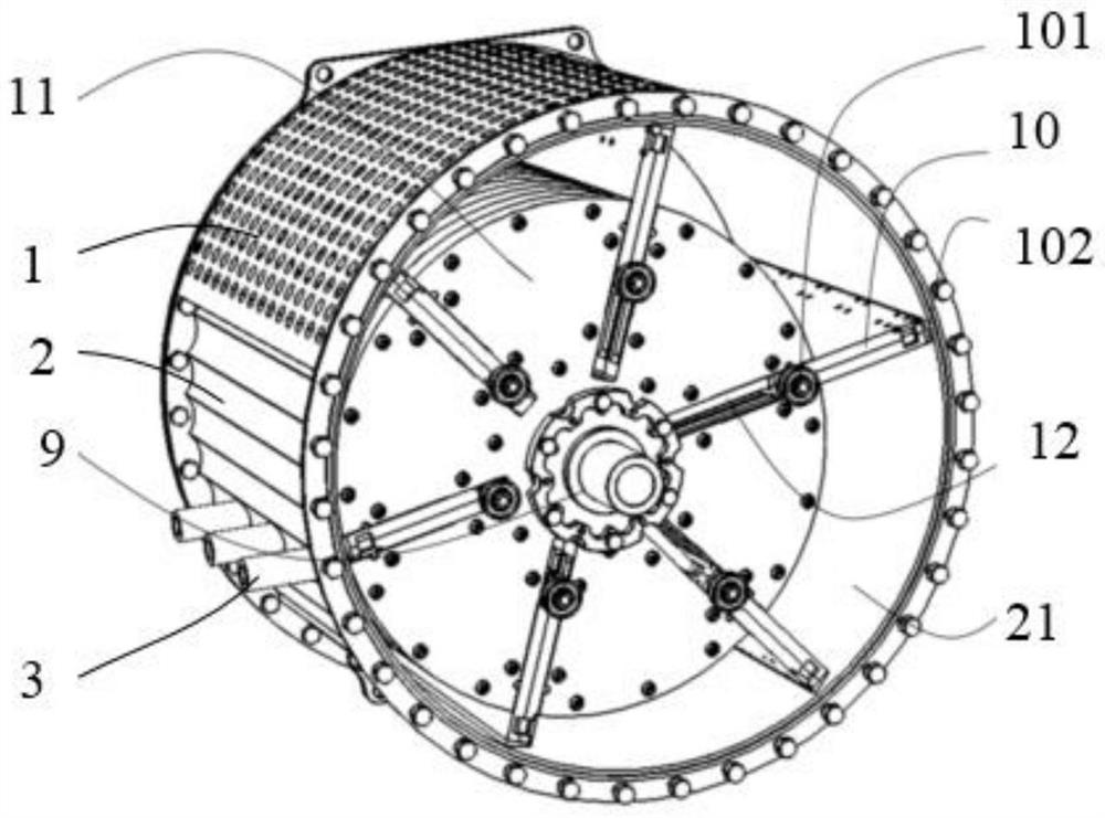
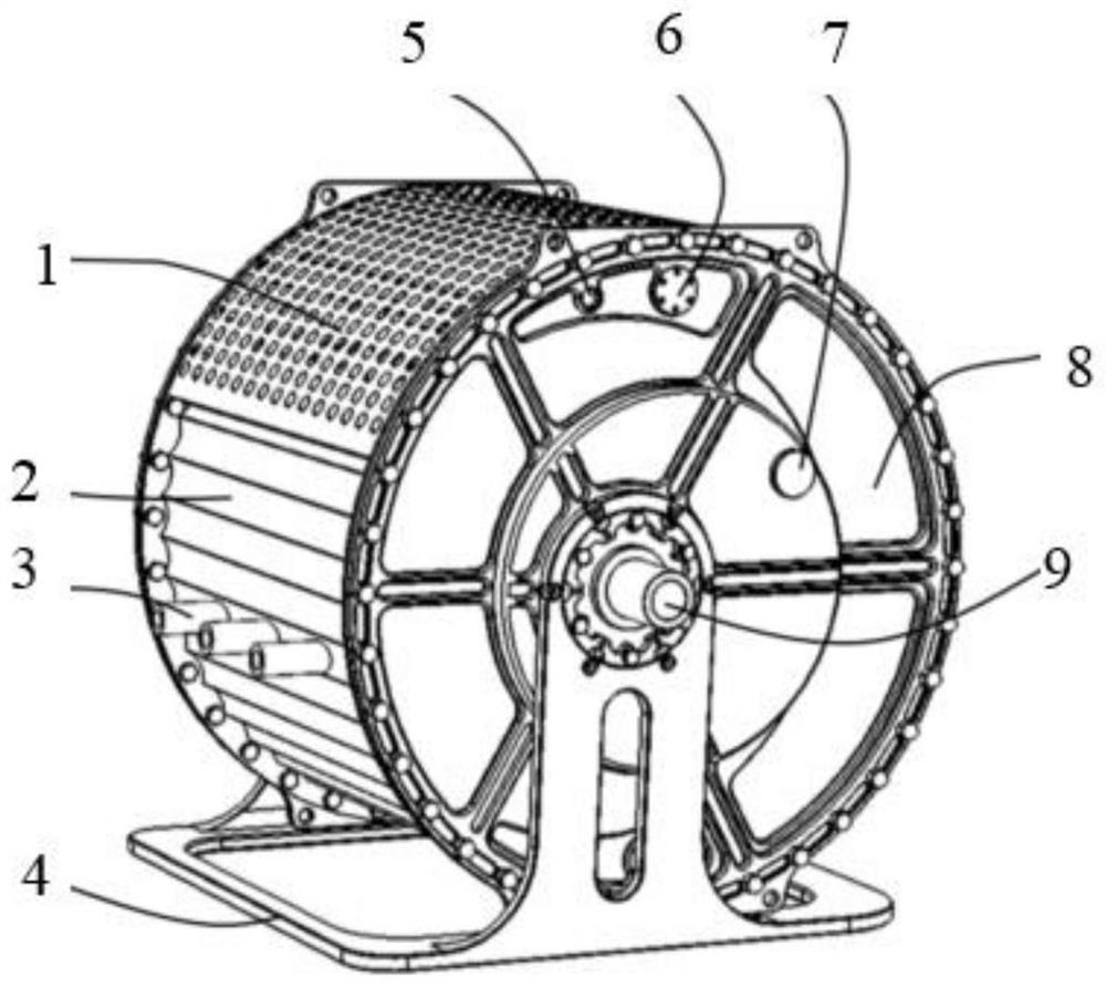
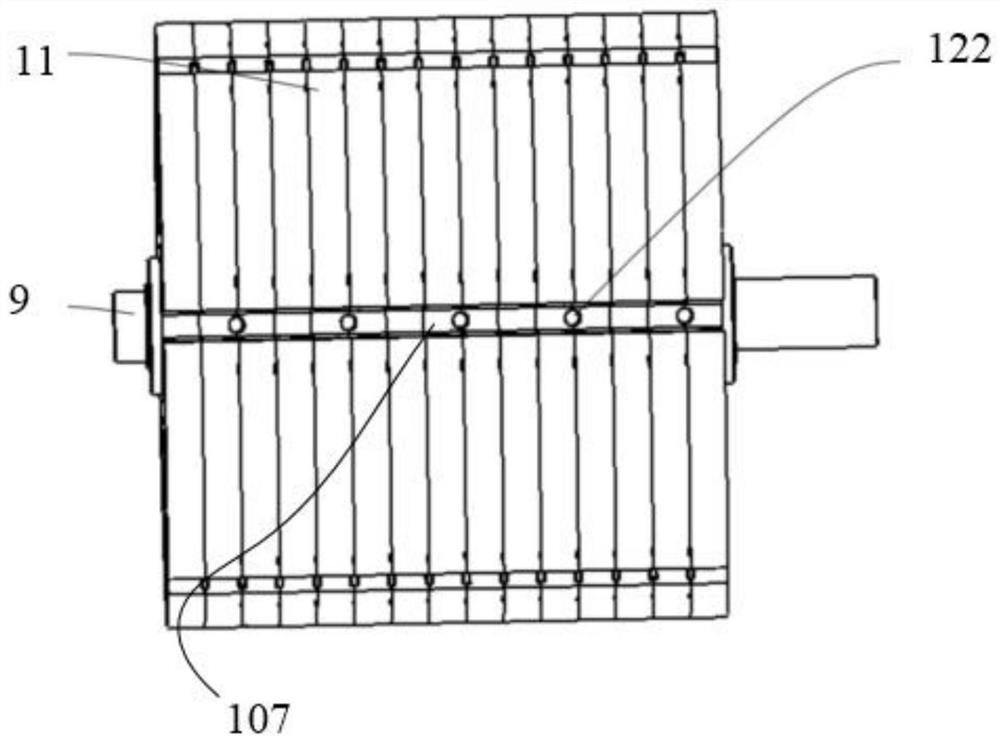
[0054] like figure 1 , image 3 and Figure 5 As shown, a power conversion device for an air compressor or a vane engine in this embodiment includes a casing 2, a rotor body 11 and a vane body 10, the casing 2 is fixedly arranged, and a cylindrical container is opened in the casing 2 The cavity, preferably, the casing 2 is a tubular structure, the rotor body 11 is a cylindrical structure, the rotor body 11 is rotatably arranged in the accommodating cavity, the axis of the rotor body 11 and the axis of the accommodating cavity are eccentrically arranged, and the rotor body 11 is provided with There are a plurality of blade grooves 107, and each blade groove 107 is slidably connected with a blade body 10. When the rotor body 11 rotates, under the action of centrifugal force, one end of each blade body 10 protruding from the rotor body 11 abuts against the casing 2. On the inner wall surface 21 of the casing, the casing 2 is provided with a first ventilation hole 1 and a second...
Embodiment 2
[0057] like figure 1 , Figure 5 , Figure 8 and Figure 10 As shown, a power conversion device for an air compressor or a vane engine in this embodiment includes all the technical features in Embodiment 1, except that the number of vane grooves 107 is an even number, for example, in a preferred In this embodiment, there are six blade grooves 107, and the included angle between the center surfaces of every two adjacent blade grooves 107 is 60°. When there are n blade grooves 107, the center surface of the adjacent blade grooves 107 The included angle between them is 360° divided by n, and each two vane slots 107 are arranged in pairs, and the two vane slots 107 arranged in pairs are located in the same plane passing through the axis of the rotor body 11. The two vane slots 107 arranged in pairs A blade connecting rod 12 is provided inside; such as Figure 5 and Figure 11 As shown, it also includes a first bushing 103 , a second bushing 104 and a third bushing 121 , and e...
Embodiment 3
[0060] like figure 1 and Figure 5 As shown, a power conversion device for an air compressor or a vane engine in this embodiment includes all the technical features in Embodiment 2, and in addition, also includes a first bearing 105, each vane groove 107 Two first bearings 105 are arranged on the end face of the rotor body 11 at the open end of the rotor In the rolling connection, the two first bearings 105 are rotated against the blade body 10. At this time, even if the blade body 10 is contacted with excessive force, a certain interval can be maintained between the rotor body 11 and the blade body 10, so that the blade connecting rod 12 With the function of the first bearing 105, there is no friction between the rotor body 11 and the vane body 10, which solves the problem that may occur with the increase of the weight of the vane when the air compressor or vane engine is made into a large product. The technology of the above large products.
[0061] The beneficial effects...
PUM
 Abstract
Description
Claims
Application Information
 - R&D
- Intellectual Property
- Life Sciences
- Materials
- Tech Scout
- Unparalleled Data Quality
- Higher Quality Content
- 60% Fewer Hallucinations
Browse by: Latest US Patents, China's latest patents, Technical Efficacy Thesaurus, Application Domain, Technology Topic, Popular Technical Reports.
© 2025 PatSnap. All rights reserved.Legal|Privacy policy|Modern Slavery Act Transparency Statement|Sitemap|About US| Contact US: help@patsnap.com


