Photovoltaic Glazing Assembly and Method

Inactive Publication Date: 2009-12-31
CARDINAL CG
View PDF99 Cites 29 Cited by
  • Summary
  • Abstract
  • Description
  • Claims
  • Application Information

AI Technical Summary

Benefits of technology

[0008]The photovoltaic glazing assembly includes a seal system, which preferably has contiguous inner and outer seals each extending between (e.g., from one to the other of) the second surfaces of the two substrates, so as to seal the first and second substrates to one another along their peripheries. The seal system bounds a narrow gas space between the two substrates. In certain preferred embodiments, the gas space has a thickness T of between approximately 0.01 inch and approximately 0.1 inch to facilitate heat tr

Problems solved by technology

The adoption of photovoltaic devices as an energy source h

Method used


Image

  • Photovoltaic Glazing Assembly and Method
  • Photovoltaic Glazing Assembly and Method
  • Photovoltaic Glazing Assembly and Method

Examples


Example

[0039]The following detailed description and figures are exemplary in nature and are not intended to limit the scope, applicability, or configuration of the invention in any way. Rather, the following description and figures provide practical illustrations for implementing exemplary embodiments of the present invention.

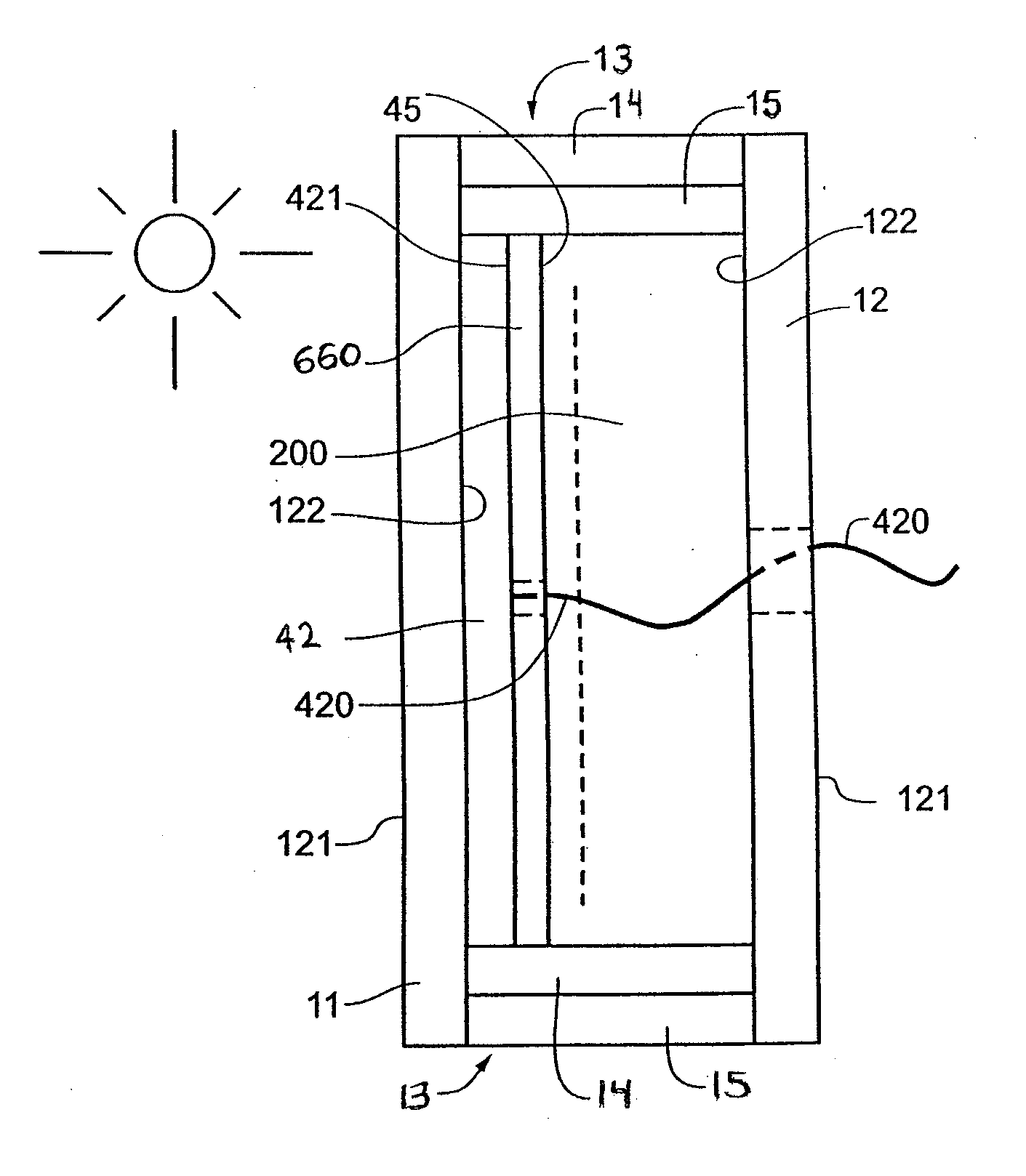
[0040]FIG. 1 is a perspective view of a photovoltaic assembly 10 according to some embodiments of the invention. FIG. 1 shows the assembly 10 including a first pane, or substrate 11, a second pane, or substrate 12 and a sealing system 13, which is between the first 11 and second 12 substrates and joins (e.g., seals) them together. The first (or “exterior”) major surfaces 121 of the substrates 11, 12 face outward (away from each other), and the second (or “interior”) major surfaces 122 face inward (toward each other). Thus, the illustrated substrates 11, 12 are spaced apart from each other by the seal system 13. The seal system 13 in FIG. 1 is shown schematically for e...


PUM


Abstract

A photovoltaic glazing assembly including first and second substrates, at least one being formed of a light transmitting material. The assembly includes a photovoltaic coating over at least the central region of a surface of the first substrate or the second substrate. In some embodiments, a seal system encloses a gas space between the substrates and optionally has a thickness of between approximately 0.01 inch and approximately 0.1 inch. Certain embodiments provide a flexible and electrically non-conductive retention film over the photovoltaic coating. Additionally or alternatively, the assembly can have a peripheral seal system with relative dimensions in certain ranges. Advantageous manufacturing methods are also provided.

Description

PRIORITY CLAIM[0001]This application is a continuation-in-part of U.S. application Ser. No. 12 / 337,441, filed on Dec. 17, 2008, which is a continuation-in-part of U.S. application Ser. No. 12 / 167,826, filed on Jul. 3, 2008, which claims priority to U.S. Provisional Application Ser. No. 61 / 043,908, filed on Apr. 10, 2008, the contents of each of which are hereby incorporated by reference. This application is also a continuation-in-part of U.S. application Ser. No. 12 / 337,853, filed on Dec. 18, 2008, which is a continuation-in-part of U.S. application Ser. No. 12 / 180,018, filed on Jul. 25, 2008, which claims priority to U.S. Provisional Application Ser. No. 61 / 025,422, filed on Feb. 1, 2008, the contents of each of which are hereby incorporated by reference.TECHNICAL FIELD[0002]The present invention pertains to photovoltaic assemblies and more particularly to photovoltaic assemblies that include at least two substrates spaced apart from each other on either side of a gas space.BACKGRO...

Claims


Application Information

Patent Timeline
IPC IPC(8): H01L31/00H01L21/50
CPCE06B3/66304Y02E10/50H01L31/206H01L31/048H01L31/0488Y02P70/50
Inventor GROMMESH, ROBERT C.PALMER, RICHARD A.O'SHAUGHNESSY, ROGER D.ZURN, BENJAMIN J.QUECK, CURT
Owner CARDINAL CG
Why Eureka
Try Eureka