Fluid processing system

Active Publication Date: 2016-08-18
GENERAL ELECTRIC CO
View PDF12 Cites 4 Cited by
  • Summary
  • Abstract
  • Description
  • Claims
  • Application Information

AI Technical Summary

Benefits of technology

[0006]Despite the impressive achievement made to date, there remains a need for improved fluid processing systems for more efficiently handling a multiphase fluid being produced from a subsea environment as well as improved energy-dissipating devices for use in such fluid processing systems.
[0007]In one embodiment, the present invention provides a fluid processing system comprising: (a) a compressor configured to receive a hot fluid comprising condensable and non-condensable components, and produce therefrom a primary compressed fluid stream and a secondary fluid stream; (b) a motor configured to drive the compressor, the motor being configured for ingress and egress of the secondary fluid stream; (c) a secondary fluid re-circulation loop configured to control an operating temperature of the motor, the secondary fluid re-circulation loop comprising a first energy-dissipating device configured to remove excess heat from the secondary fluid stream, the first energy dissipating device comprising (i) an inlet header, (ii) an outlet header, (iii) a plurality of heat exchange tubes, and (iv) at least one passive gas-liquid separator; (d) a purge line configured to separate a first portion of the secondary fluid stream in the fluid re-circulation loop from a second portion of the secondary fluid stream being returned to the motor; and (e) a fluid conduit configured to receive the pr

Problems solved by technology

The relatively cold temperature of the subsurface environment notwithstanding, motors used in subsurface installations are prone to damage caused by overheating.
However, the variability of production fluid compositions, temperatures and pressures, may limit the utility of suc

Method used


Image

  • Fluid processing system
  • Fluid processing system
  • Fluid processing system

Examples


Example

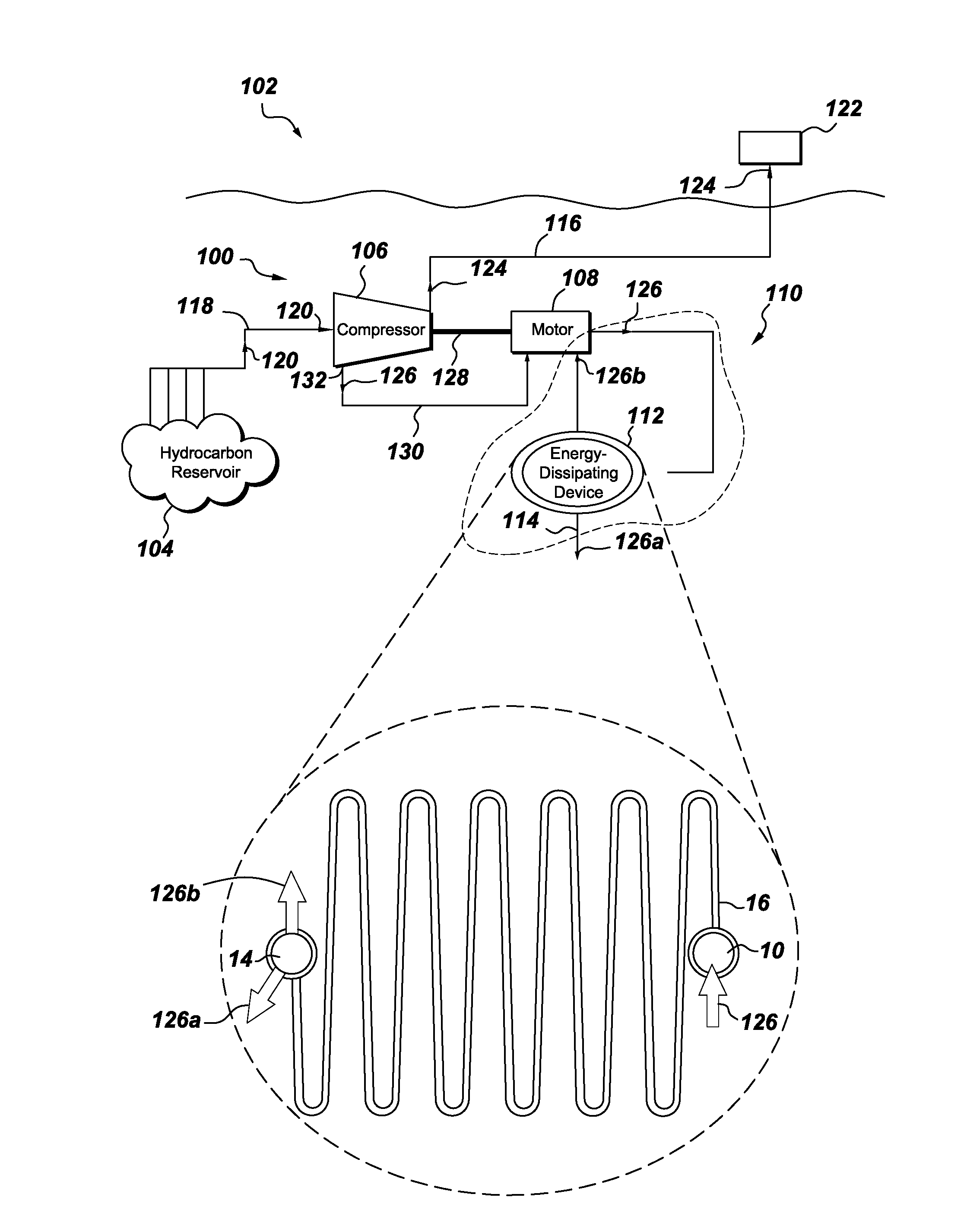
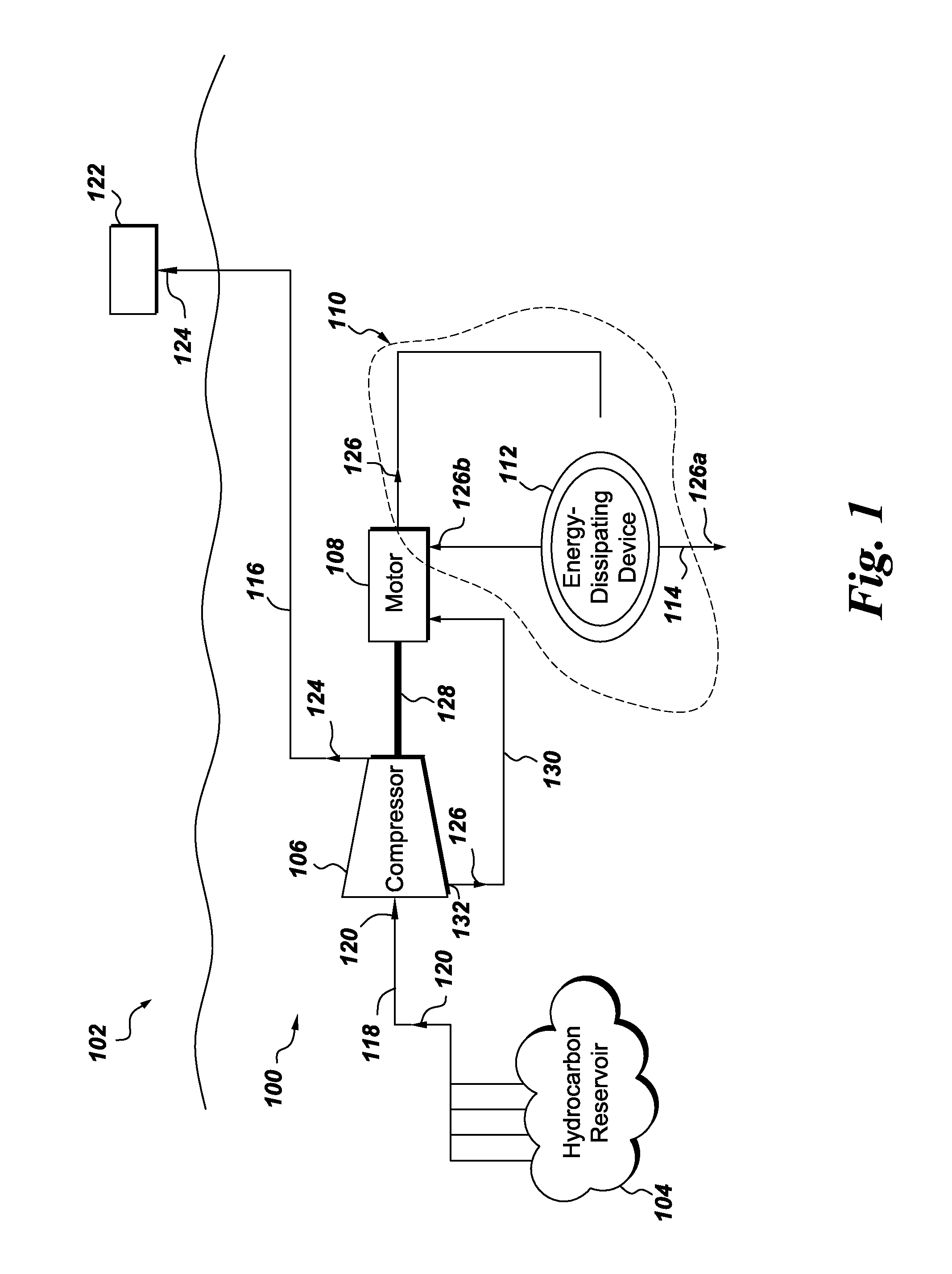
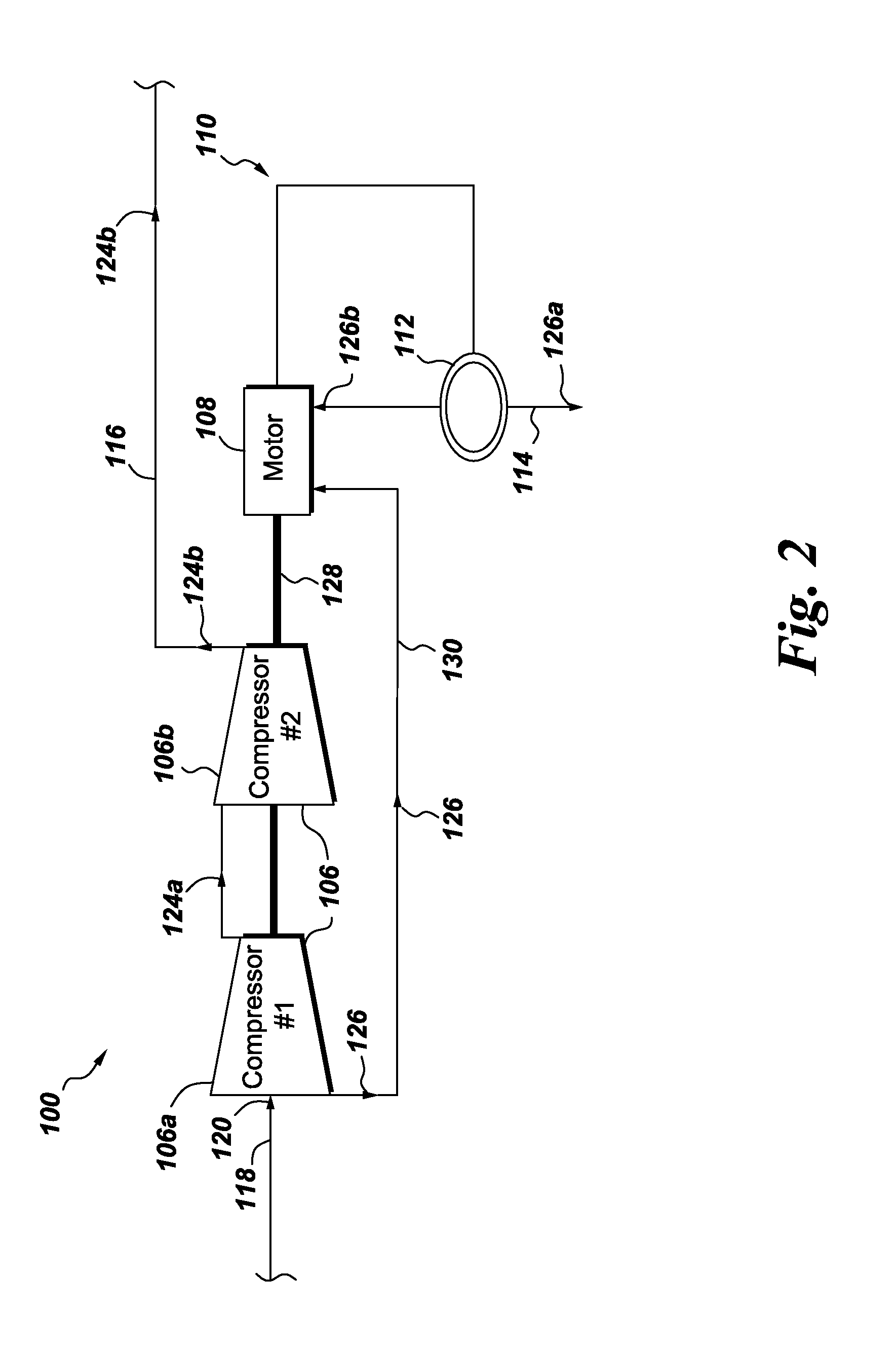
[0025]Embodiments discussed herein disclose a new configuration of a fluid processing system for efficiently moving multiphase fluid being produced from a subsea hydrocarbon reservoir to a distant fluid storage facility. The fluid processing system of the present invention comprises an energy-dissipating device disposed upstream and / or downstream relative to a compressor and a fluid re-circulation loop. The energy-dissipating device comprises at least one at least one passive gas-liquid separator, but may further comprise one or more of a heat exchange sub-system, a work extraction device, and a pressure changing device, which may or may not effect the passive separation of the gaseous and liquid components of the fluid being processed. The energy-dissipating device is configured to remove excess heat from a fluid stream and produce therefrom a first portion of a heat depleted fluid stream enriched in condensable components and a second portion of the heat depleted fluid stream depl...


PUM

PropertyMeasurementUnit
Energyaaaaaaaaaa

Abstract

An energy-dissipating device and fluid processing system is provided containing a compressor, a motor, a secondary fluid re-circulation loop, a purge line, and a fluid conduit. The compressor is configured to receive a hot fluid including condensable and non-condensable components, and produce therefrom a primary compressed fluid stream and a secondary fluid stream. The motor is configured to drive the compressor and for ingress and egress of the secondary fluid stream. The secondary fluid re-circulation loop is configured to control an operating temperature of the motor. The secondary fluid re-circulation loop includes a first energy-dissipating device configured to remove excess heat from the secondary fluid stream. The purge line separates a first portion of the secondary fluid stream in the fluid re-circulation loop from a second portion of the secondary fluid stream being returned to the motor. The fluid conduit receives the primary compressed fluid stream from the compressor.

Description

CROSS REFERENCE TO RELATED APPLICATIONS[0001]This application is a Continuation-In-Part of and claims priority from U.S. patent application Ser. No. 14 / 490,183 filed on 18 Sep. 2014, and which is incorporated by reference herein in its entirety.BACKGROUND[0002]The present invention relates to fluid processing systems for deployment in subsea environments, and energy-dissipating devices used in such fluid processing systems.[0003]Fluid processing systems used for hydrocarbon production in subsea environments typically include a main separator assembly and a heat exchange system disposed upstream relative a compressor. The heat exchange system reduces temperature of a multiphase fluid extracted from a subsea hydrocarbon reservoir. The main separator assembly receives the multiphase fluid from the heat exchange system and separates gaseous components from liquid components of the multiphase fluid.[0004]In such fluid processing systems motors may be provided to drive one or more compres...

Claims


Application Information

Patent Timeline
IPC IPC(8): E21B43/34B01D19/00F28F9/02F28D1/02F28F23/00
CPCE21B43/34F28F9/02F28F23/00F28F9/0265F28F9/0275B01D19/0057B01D19/0068F28D2021/004B01D19/0073C10L3/06C10L3/10C10L3/101E21B43/36F15D1/14F04D17/08F04D25/0686F04D29/5806F04D31/00F28D1/022E21B36/001F04D29/5866F04D29/5826F04D13/086
Inventor FRIEDEMANN, JOHN DANIELMELE, ERIKERICSSON, ALBERT ERIK JOHANNES
Owner GENERAL ELECTRIC CO
Why Eureka
Try Eureka