Compression tool

Inactive Publication Date: 2006-10-12
DETROIT DIESEL
View PDF15 Cites 2 Cited by
  • Summary
  • Abstract
  • Description
  • Claims
  • Application Information

AI Technical Summary

Benefits of technology

[0007] The present invention is directed to a compression tool that enables efficient handling and installation of a compressible component. The compression tool includes a first handle having a proximal end and a working end. The working end includes a first engaging member. The tool further includes a second handle pivotally attached to the first handle and having a proximal end and a working end. The working end also includes a second engaging member. The first and second engaging members are maintained in opposed alignment and have an orifice defined by an engageable flange portion.

Problems solved by technology

However, this approach has several disadvantages including the inevitable fatigue of the installer's hand as well as the inherent risk of damaging bellows 10 due to mishandling as a result of “bare” hand installation.

Method used


Image

  • Compression tool
  • Compression tool
  • Compression tool

Examples


Embodiment Construction

)

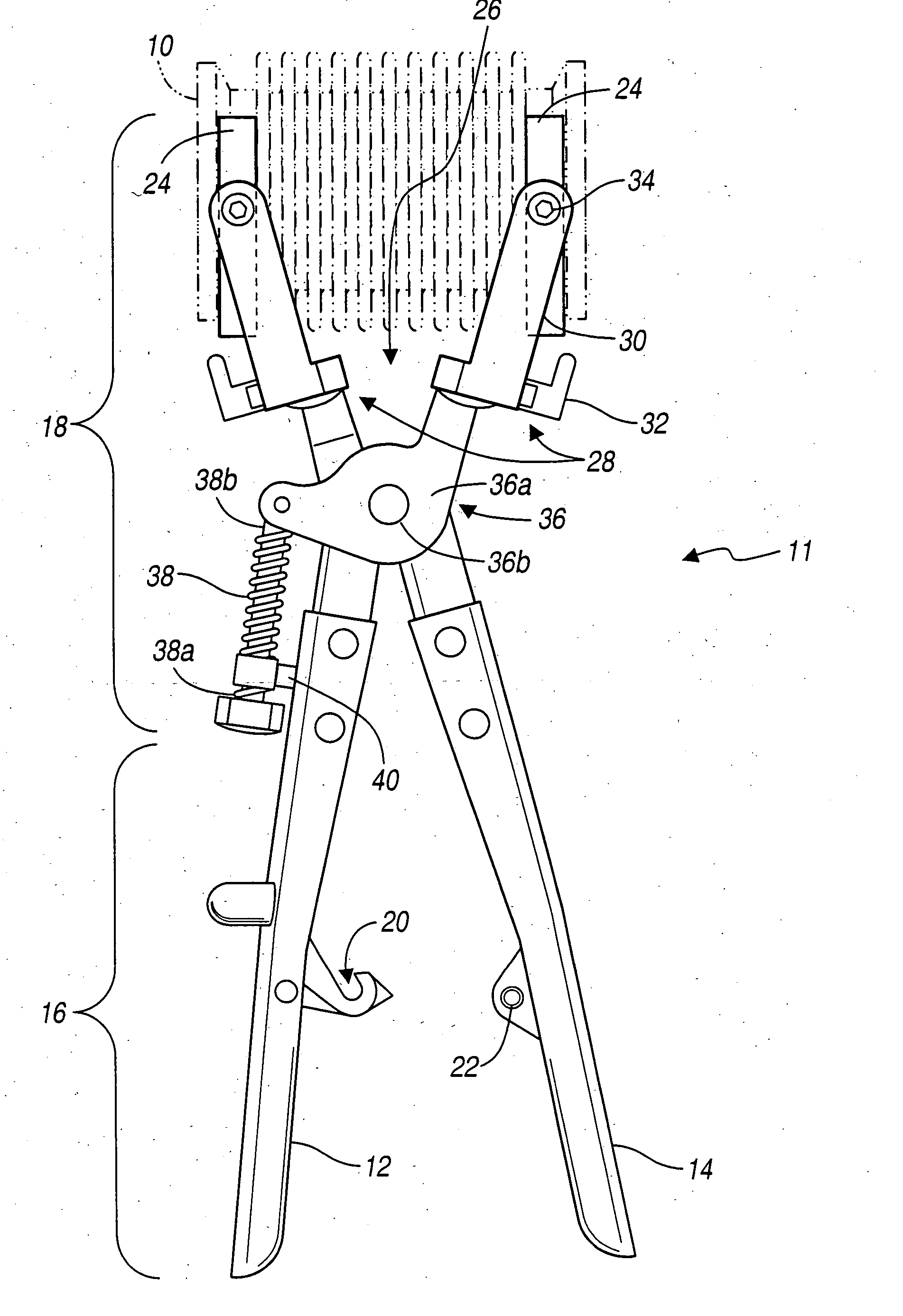
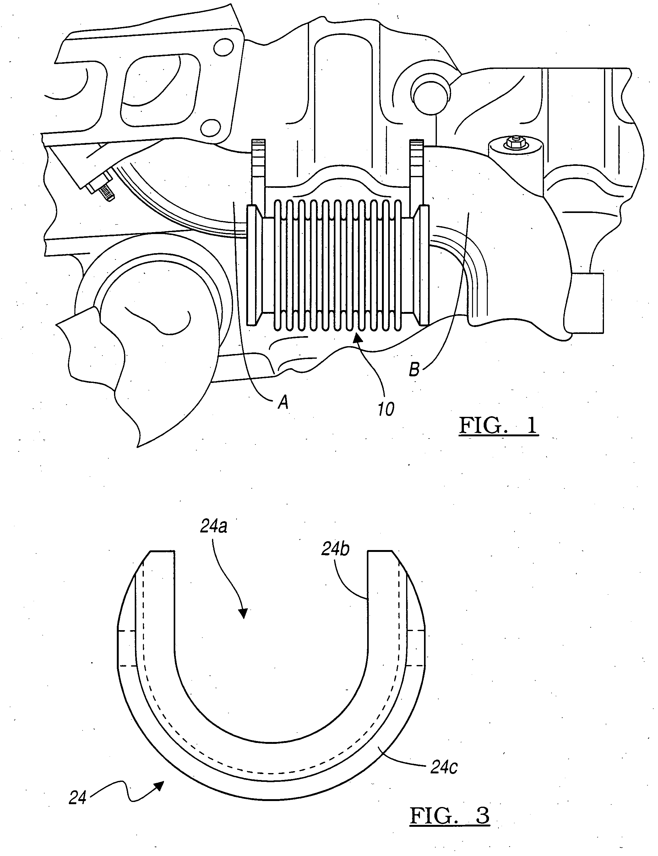
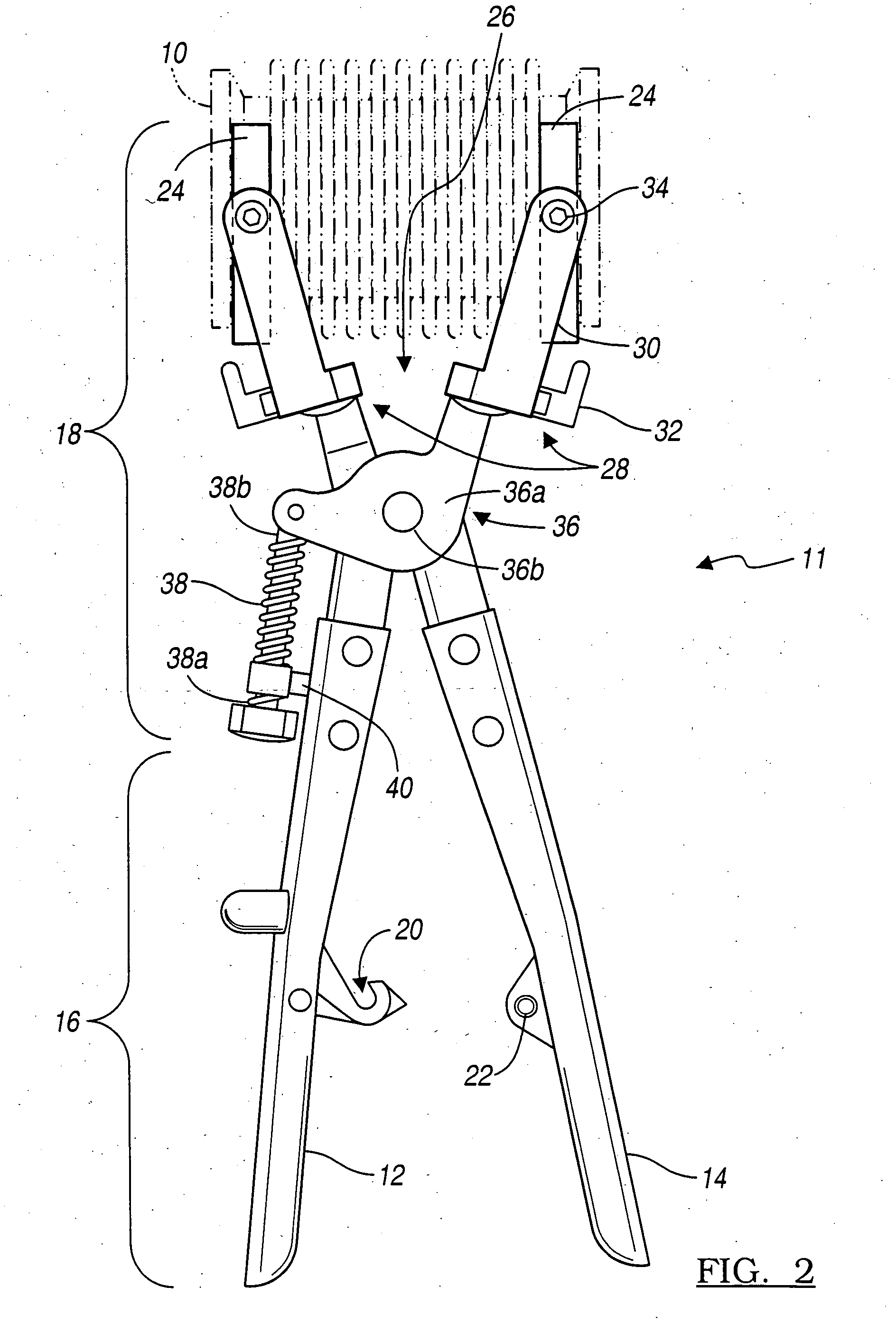
[0013] Referring to FIG. 2, a compression tool 11 is illustrated that enables efficient handling and installation of a compressible component. By way of example and not limitation, the compressible component described is represented as the bellows 10 of FIG. 1. It is recognized, however, that compression tool 11 may be adapted or modified for use with virtually any compressible component or member without departing from the scope of the invention. Accordingly, compression tool 11 includes a first handle 12 and a second handle 14. The first and second handles 12 and 14 each have a proximal end 16 and a working end 18.

[0014] At proximal end 16 the first and second handles 12 and 14 include a latching mechanism. As such, a latch 20 is connected to first handle 12 and a receiving member 22 is connected to second handle 14. Latch 20 is configured to engage receiving member 22 thereby locking first and second handles 12 and 14. The locking function disables movement of first and second ...


PUM


Abstract

A compression tool enables efficient handling, compression, and installation of a compressible component. The compression tool includes a first handle having a proximal end and a working end, wherein the working end has a first engaging member. The tool further includes a second handle pivotally attached to the first handle and having a proximal end and a working end. The working end also includes a second engaging member. The first and second engaging members are maintained in opposed alignment. Furthermore, the first and second engaging members have an orifice defined by an engageable flange portion configured to engage the compressible component.

Description

BACKGROUND OF THE INVENTION [0001] 1. Field of the Invention [0002] The present invention relates generally to improved tool and more specifically to improved tool for compressing compressible components. [0003] 2. Background Art [0004] The use of substantially rigid, yet flexible components on vibrating machines is common. In many cases, these components are utilized as conduits for the passage of gasses and liquids. It is common for these components to be included in a ducting system such as an exhaust system, wherein the component is attached to other rigid members within the system. An example of such a component is a flexible bellows 10 as shows in FIG. 1. The bellows 10 is configured to maintain an airtight seal with adjacent exhaust system components (e.g., components A and B of FIG. 1) for the passage of gasses or liquids throughout an exhaust system of a vehicle despite engine vibration and movement. Accordingly, bellows 10 is designed to maintain a sufficient amount of rig...

Claims


Application Information

Patent Timeline
IPC IPC(8): B25B7/02B25B25/00
CPCB25B7/02B25B27/30B25B7/04
Inventor MOSEY, JAMES RICHARD
Owner DETROIT DIESEL
Why Eureka
Try Eureka