Mounting and positioning structure for wall-mounted heating stove

A technology for installation and positioning of heating furnaces, applied in the field of heating furnaces, can solve problems affecting space utilization, inconvenient shifting, and inability to move, and achieve the effects of convenient inspection, cleaning, and optimized space utilization

Inactive Publication Date: 2022-07-29
江苏万高新能源科技发展有限公司
View PDF0 Cites 0 Cited by
  • Summary
  • Abstract
  • Description
  • Claims
  • Application Information

AI Technical Summary

Problems solved by technology

[0003] When the wall-mounted heating furnace is installed and positioned, it is usually fixed on the wall by a bracket and cannot be moved. When inspection is required, the entire furnace body generally needs to be disassembled to inspect the back, which is cumbersome, and the fixed installation structure , it is inconvenient to shift and affects space utilization. Therefore, the present invention proposes an installation and positioning structure for a wall-mounted heating furnace to solve the problems existing in the prior art

Method used


Image

  • Mounting and positioning structure for wall-mounted heating stove
  • Mounting and positioning structure for wall-mounted heating stove
  • Mounting and positioning structure for wall-mounted heating stove

Examples


Embodiment 1

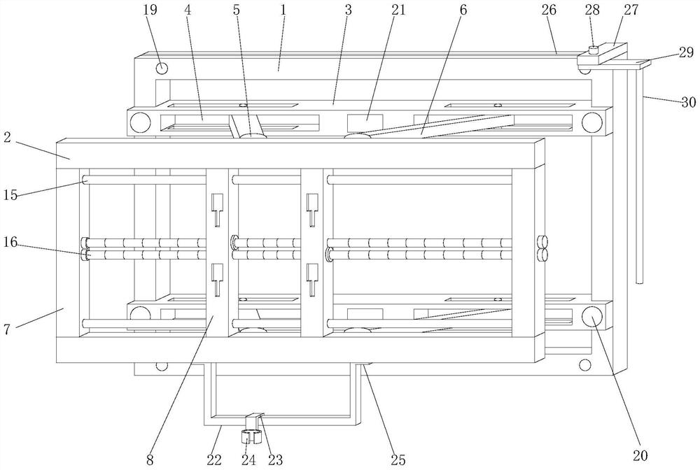
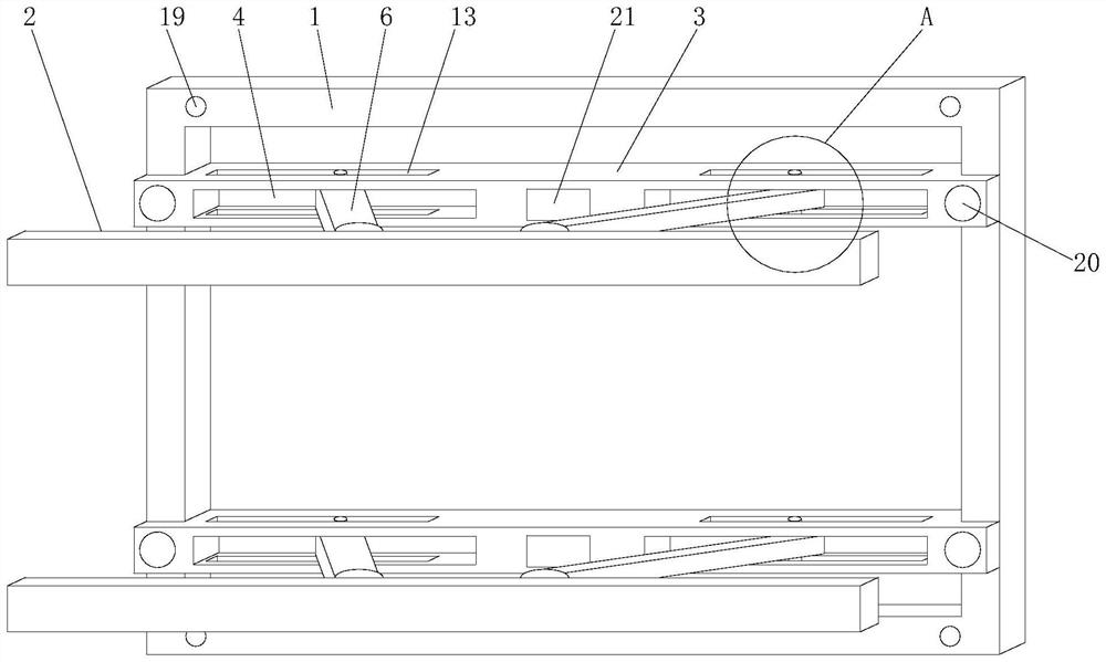
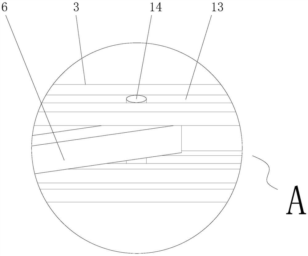
[0030] according to figure 1 , 2 , 3, 4, 5, and 6, this embodiment proposes a mounting and positioning structure for a wall-mounted heating furnace, including a positioning frame 1 and an adjustment frame 2, and the upper and lower ends of the positioning frame 1 are provided with mounting and positioning structures. Frame 3, and both sides of the front end of the mounting frame 3 are provided with movable grooves 4, the adjustment frame 2 is provided with two upper and lower groups, and both sides of the rear end of the adjustment frame 2 of the two groups are provided with shaft plates 5. A support arm 6 is rotatably installed on the shaft plate 5, and the rear ends of the support arms 6 on both sides of the adjustment frame 2 are respectively movably installed with the movable grooves 4 on both sides and are limited by the limiting parts;

[0031] Connecting rods 7 are provided on both sides between the two sets of adjustment frames 2 , and an adjusting portion is provided...

Embodiment 2

[0037] according to figure 1 , 5 As shown, the present embodiment proposes a mounting and positioning structure for a wall-mounted heating furnace, including a positioning frame 1 and an adjusting frame 2. The upper and lower ends of the positioning frame 1 are provided with mounting frames 3, and the front end of the mounting frame 3 is provided with a mounting frame 3. Both sides are provided with movable grooves 4, the adjusting frame 2 is provided with two upper and lower groups, and both sides of the rear end of the adjusting frame 2 of the two groups are provided with shaft plates 5, and the shaft plates 5 are rotatably installed with support Arm 6, the rear ends of the support arms 6 on both sides of the adjusting frame 2 are respectively movably installed with the movable grooves 4 on both sides and are limited by the limiting parts;

[0038] Connecting rods 7 are provided on both sides between the two sets of adjustment frames 2 , and an adjusting portion is provided...

Embodiment 3

[0041] according to figure 1 , 5 As shown, the present embodiment proposes a mounting and positioning structure for a wall-mounted heating furnace, including a positioning frame 1 and an adjusting frame 2. The upper and lower ends of the positioning frame 1 are provided with mounting frames 3, and the front end of the mounting frame 3 is provided with a mounting frame 3. Both sides are provided with movable grooves 4, the adjusting frame 2 is provided with two upper and lower groups, and both sides of the rear end of the adjusting frame 2 of the two groups are provided with shaft plates 5, and the shaft plates 5 are rotatably installed with support Arm 6, the rear ends of the support arms 6 on both sides of the adjusting frame 2 are respectively movably installed with the movable grooves 4 on both sides and are limited by the limiting parts;

[0042] Connecting rods 7 are provided on both sides between the two sets of adjustment frames 2 , and an adjusting portion is provided...


PUM


Abstract

The invention provides a mounting and positioning structure for a wall-mounted heating stove, and relates to the technical field of heating stoves, the mounting and positioning structure comprises a positioning frame and adjusting frames, mounting frames are arranged at the upper end and the lower end in the positioning frame, movable grooves are formed in the two sides of the front end of each mounting frame, and the upper adjusting frame and the lower adjusting frame are arranged; shaft plates are arranged on the two sides of the rear ends of the two sets of adjusting frames, supporting arms are rotationally installed on the shaft plates, and the rear ends of the supporting arms on the two sides of the adjusting frames are movably installed with the movable grooves in the two sides correspondingly and limited through limiting parts. The heating stove body is installed on the fixing plate, when the back face of the heating stove body needs to be inspected, the heating stove body is pulled, the adjusting frame is driven to move forwards, the adjusting frame can be conveniently stretched forwards through the rotation effect of the supporting arm and the shaft plate and the movement effect of the supporting arm and the movable groove, and the back face of the heating stove body can be conveniently inspected. Therefore, the heating stove body is stretched forwards to inspect the back face, and inspection is more convenient.

Description

technical field [0001] The invention relates to the technical field of heating stoves, in particular to an installation and positioning structure for a wall-mounted heating stove. Background technique [0002] The full name of the wall-mounted heating furnace is: "gas wall-mounted heating furnace", with anti-freeze protection, anti-dry protection, accidental flameout protection, over-temperature protection, water pump anti-jamming protection and other safety protection measures. It is a mature product that has been popular in Europe for decades. The term "wall-hung boiler" is a foreign term. The wall-hung heating furnace can be connected to an indoor temperature controller to achieve personalized temperature regulation and energy saving. According to statistics, the use of indoor temperature controllers It can save 20-28% of gas costs; [0003] When the wall-mounted heating furnace is installed and positioned, it is usually fixed on the wall through a bracket and cannot be ...

Claims


Application Information

Patent Timeline
Patent Type & Authority Applications(China)
IPC IPC(8): F24D15/02F24D19/02B08B1/00
CPCF24D15/02F24D19/0209F24D19/0246B08B1/008
Inventor 王峰刘元
Owner 江苏万高新能源科技发展有限公司
Why Eureka
Try Eureka