Crimping jig for batch testing and testing equipment

A batch testing and jig technology, applied in the direction of measuring electricity, measuring devices, measuring electrical variables, etc., can solve problems such as low efficiency, and achieve the effect of improving efficiency and avoiding up and down movement.

Active Publication Date: 2022-08-02
武汉精毅通电子技术有限公司 +1
View PDF8 Cites 0 Cited by
  • Summary
  • Abstract
  • Description
  • Claims
  • Application Information

AI Technical Summary

Problems solved by technology

[0004] However, the connectors of the display panel are usually arranged protruding from the surface of the test board, and the connectors of each display panel need to be placed in the positioning grooves of the mold core fixing seats on the crimping parts during the test to align The probes in the connector a

Method used


Image

  • Crimping jig for batch testing and testing equipment
  • Crimping jig for batch testing and testing equipment
  • Crimping jig for batch testing and testing equipment

Examples


Embodiment Construction

[0030] In order to make the objectives, technical solutions and advantages of the present invention clearer, the present invention will be further described in detail below with reference to the accompanying drawings and embodiments. It should be understood that the specific embodiments described herein are only used to explain the present invention, but not to limit the present invention. In addition, the technical features involved in the various embodiments of the present invention described below can be combined with each other as long as there is no conflict with each other.

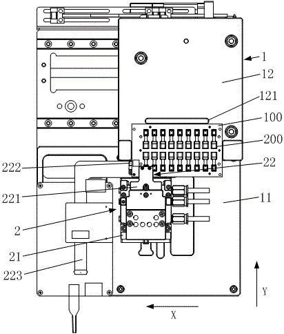
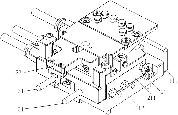
[0031] figure 1 It is a schematic structural diagram of a crimping jig for batch testing provided by an embodiment of the present invention, figure 2 It is a partial cross-sectional view of a crimping jig for batch testing provided by an embodiment of the present invention in a crimping state, combined with figure 1 and figure 2 As shown, the crimping fixture includes a support assembly 1 , a c...


PUM


Abstract

The invention discloses a crimping jig for batch testing and testing equipment, and belongs to the field of display panel testing. The crimping jig comprises a supporting assembly, a crimping assembly and an adjusting assembly. The supporting assembly comprises a bottom plate and a carrier plate. The crimping assembly comprises a movable part and a crimping part, and the crimping part comprises a pressing head and a mold core fixing seat which are oppositely arranged. The adjusting assembly comprises a pin shaft and a lifting block, the pin shaft is inserted into the movable part and extends in the Y-axis direction, the mold core fixing base is located on the lifting block, the lifting block is connected with the bottom plate through an elastic part, a notch is formed in the bottom of the lifting block, the top of the notch is an inclined face used for making contact with the pin shaft, and the pin shaft is movably inserted into the notch. According to the crimping jig for batch testing provided by the embodiment of the invention, the connector can be automatically inserted into or separated from the positioning groove, and the test board is prevented from frequently moving up and down, so that the efficiency of batch testing is improved.

Description

technical field [0001] The invention belongs to the field of display panel testing, and more particularly, relates to a crimping fixture and testing equipment for batch testing. Background technique [0002] With the rapid development of display panels, traditional LED and OLED display technologies will gradually be replaced by Microled. In the early stage of research and development of Microled, limited by the massive transfer process, it can only be produced in small size. [0003] In the related art, small-sized display panels such as Microled are inconvenient to grab and move. In order to improve the test efficiency, multiple display panels are usually inserted into the test board at even intervals. After the test is completed, the test board only needs to be moved by one unit. The distance is such that the connector of the next display panel is facing the crimping piece, so as to realize batch testing. [0004] However, the connectors of the display panels are usually...

Claims


Application Information

Patent Timeline
IPC IPC(8): G01R31/00G01R1/04
CPCG01R31/00G01R1/04G01R1/0416
Inventor 江慕磊明翔罗回吉海洋
Owner 武汉精毅通电子技术有限公司
Why Eureka
Try Eureka