
Frame extension joint structure

A joint structure and frame technology, which is applied in the direction of pivot connection, mechanical equipment, engine components, etc., can solve the problems of low docking accuracy, skewed joints, skewed joints, etc., and achieve fast and accurate folding without loosening and shaking , high folding efficiency

Active Publication Date: 2022-08-05
殷际良
View PDF4 Cites 0 Cited by
  • Summary
  • Abstract
  • Description
  • Claims
  • Application Information

AI Technical Summary

Problems solved by technology

[0002] The movable joint is used in the rigid relative rotation between steel parts. However, during the rotation process, there will be relative shaking between the two steel parts, which will cause the joint of the two steel parts to be skewed after stretching, resulting in the accuracy of the joint. Low, mobile joints are easy to loosen
For example, in the field of folding track technology, if the two sections of the track are stretched, the joint of the two sections of the track will be skewed and skewed, and it will not be on a smooth track, which will affect the stability of the running parts.

Method used


Image

  • Frame extension joint structure
  • Frame extension joint structure
  • Frame extension joint structure

Examples


Embodiment Construction

[0028] In order to have a clearer understanding of the technical features, purposes and effects of the present invention, the specific embodiments of the present invention will now be described with reference to the accompanying drawings. The same reference numerals in each figure represent components with the same structure or similar structure but the same function.

[0029] Many specific details are set forth in the following description to facilitate a full understanding of the present invention. However, the present invention can also be implemented in other ways different from those described herein. Therefore, the protection scope of the present invention is not limited by the specific details disclosed below. Example limitations.

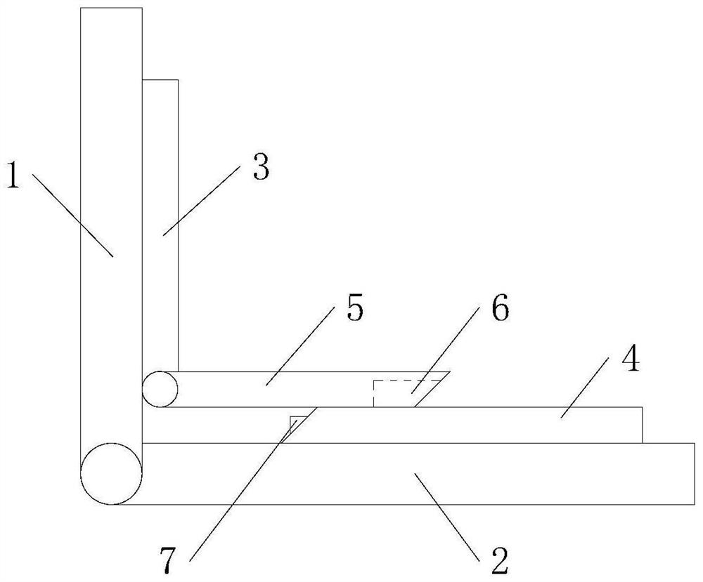
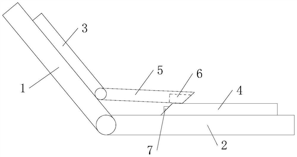
[0030] refer to Figure 1 to Figure 6 , the present application proposes a frame extension joint structure, which includes a first joint part 1, a second joint part 2, a first butt joint 3, a second butt joint 4 and a butt tongue 5, wherein ...


PUM


Abstract

The invention discloses a frame extension joint structure which comprises a first joint piece, a second joint piece, a first butt joint piece, a second butt joint piece and a butt joint tongue, the first joint piece is rotationally hinged to the second joint piece, the first butt joint piece is fixedly connected with the first joint piece, the first butt joint piece is rotationally hinged to the butt joint tongue, and the second butt joint piece is fixedly connected with the butt joint tongue. The second butt joint piece is fixedly connected with the second joint piece; the butt joint face of the butt joint tongue and the second butt joint piece is an inclined face, a butt joint groove is formed in one of the butt joint ends of the butt joint tongue and the second butt joint piece, a protruding butt joint block is arranged on the other butt joint end of the butt joint tongue and the second butt joint piece, and the butt joint block slides along the butt joint groove. The first joint piece and the second joint piece rotate and stretch, the butt joint tongue can slide in the direction from the butt joint face to the second joint piece, the butt joint block enters the butt joint groove, and the butt joint tongue is in butt joint with the second butt joint piece. When the first joint piece and the second joint piece rotate and stretch, the butt joint block enters the butt joint groove, the butt joint process is guided and limited, the butt joint position of the butt joint tongue and the second butt joint piece is prevented from inclining, and the butt joint precision is improved.

Description

technical field [0001] The invention relates to the technical field of frame extension movable joints, in particular to a frame extension joint structure. Background technique [0002] The movable joint is used in the rigid relative rotation between the steel parts. However, during the rotation process, there will be relative shaking between the two steel parts, causing the butt joint of the two steel parts to be skewed after stretching, resulting in the accuracy of the butt joint. Low, movable joints are prone to loosening problems. For example, in the technical field of folding rails, if the two rails are stretched, the butt joints of the two rails are offset and skewed, which is not on a smooth track, which will affect the stability of the walking member. [0003] How to improve the docking accuracy in the extension direction of the movable joint needs to be solved urgently. SUMMARY OF THE INVENTION [0004] In order to solve the technical problem of how to improve th...

Claims


Application Information

Patent Timeline
Patent Type & Authority Applications(China)
IPC IPC(8): F16C11/04F16N1/00
CPCF16C11/04F16N1/00Y02E10/50
Inventor 殷际良
Owner 殷际良
Learn More